A4Q AUTOMATIC TRANSMISSION / TRANSAXLE AUTOMATIC TRANSMISSION UNIT REASSEMBLY
PROCEDURE

 1. BEARING POSITION
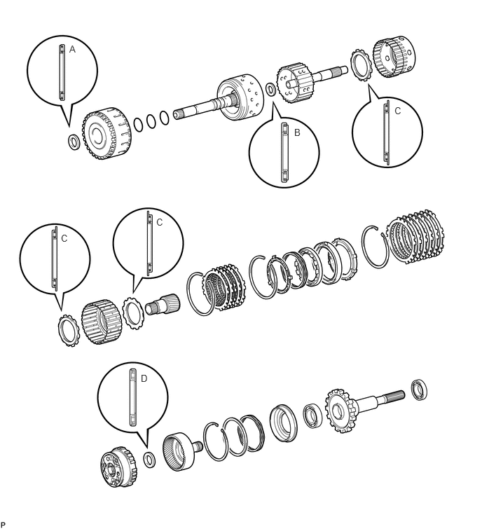
| Mark | Thrust Bearing Outside Diameter
mm (in.) |
Thrust Bearing Inside Diameter
mm (in.) |
|---|---|---|
| A | 44.5 (1.752) | 29.7 (1.169) |
| B | 30.0 (1.181) | 14.0 (0.551) |
| C | 57.0 (2.244) | 41.4 (1.630) |
| D | 44.5 (1.752) | 29.7 (1.169) |
G1406
2.INSTALL TRANSMISSION SOLENOID CONNECTOR SUB-ASSEMBLY
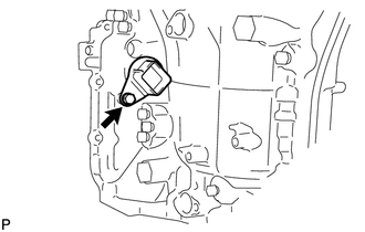
Coat a new O-ring with Toyota Genuine ATF Type T-IV, and install it to the transmission solenoid connector sub-assembly.
Install the transmission solenoid connector sub-assembly with the bolt.
- Torque:
- 8.4 N*m (85 kgf*cm, 74 in.*lbf)
35623H
3.INSTALL 1ST AND REVERSE BRAKE PISTON
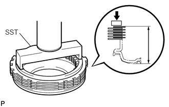
Assemble the brake clutch discs and brake plates on the 1st and reverse brake piston.
Using SST and a press, press the assembly with 19.6 N (2.00 kg, 4.41 lb).
- SST
- 09350-32014 (09351-32040)
Measure the assembly height.
Based on this assembly height, select a suitable flange according to the table below.
| Assembly height | Flange thickness | Mark |
|---|---|---|
| 39.450 to 39.661 mm
(1.55314 to 1.56145 in.) |
4.0 mm (0.157 in.) | 0 |
| 39.250 to 39.450 mm
(1.54527 to 1.55314 in.) |
4.2 mm (0.165 in.) | 1 |
| 39.050 to 39.250 mm
(1.53740 to 1.54527 in.) |
4.4 mm (0.173 in.) | 2 |
| 38.850 to 39.050 mm
(1.52952 to 1.53740 in.) |
4.6 mm (0.181 in.) | 3 |
| 38.650 to 38.850 mm
(1.52165 to 1.52952 in.) |
4.8 mm (0.189 in.) | 4 |
| 38.439 to 38.650 mm
(1.51334 to 1.52165 in.) |
5.0 mm (0.197 in.) | 5 |
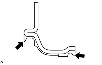
Coat a new 1st and reverse brake piston with Toyota Genuine ATF Type T-IV, and install it to the transmission case.
Install the 1st and reverse brake piston return spring and 1st and reverse brake piston return spring seat.
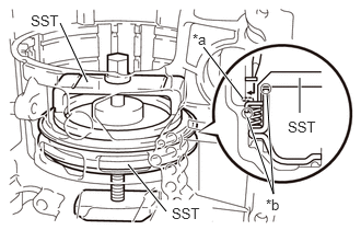
| *a | Groove |
| *b | Deformation |
Place SST on the 1st and reverse brake piston return spring seat and compress the 1st and reverse brake piston return spring.
- SST
- 09351-87201
09351-97201
- HINT:
-
To prevent deformation, be sure to stop tightening the SST when the spring has been lowered 1 to 2 mm (0.04 to 0.08 in.) from the snap ring installation groove.
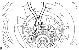
Using snap ring pliers, install the hole snap ring.
35775F
4.INSTALL RADIAL BALL BEARING
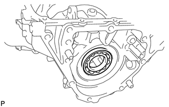
Install the radial ball bearing to the transmission case.
35740
5.INSTALL FRONT PLANETARY RING GEAR ASSEMBLY
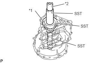
| *1 | Front Planetary Ring Gear Assembly |
| *2 | Press |
Using SST and a press, install the front planetary ring gear assembly into the transmission case.
- SST
- 09308-14010
09309-14010
09309-35010
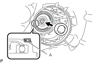
Install the thrust needle roller bearing to the front planetary ring gear assembly.
- HINT:
-
Be sure to install with the A section of the bearing facing toward the output shaft side.
35666B
6.INSTALL BRAKE CLUTCH DISC
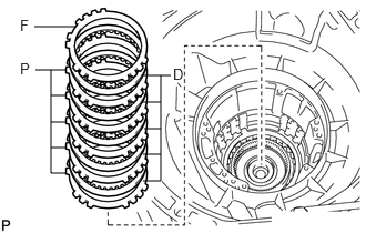
Install the 5 brake plates, 5 brake clutch discs and the brake flange.
- Install in order:
P = Brake plate, D = Brake clutch disc, F = Brake flange
P - D - P - D - P - D - P - D - P - D - F
- HINT:
- ·
Before installing new brake clutch discs, soak them in the Toyota Genuine ATF Type T-IV for at least 15 minutes.
·Be sure to align the cut-out section of the brake plates and brake flange when installing the brake plate.
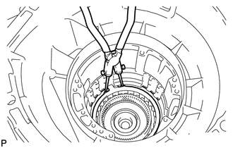
Using snap ring pliers, install the hole snap ring.
35720L
7.INSTALL PLANETARY GEAR ASSEMBLY
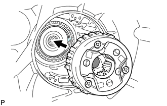
Install the planetary gear assembly to the transmission case.
- HINT:
-
Ensure that the assembly rotates smoothly.
35790E
8.INSTALL 1 WAY CLUTCH ASSEMBLY
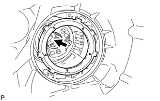
Install the 1 way clutch assembly into the transmission case.
- HINT:
- ·
Make sure that the 1 way clutch assembly and the hole snap ring are installed in the correct direction.
·Align the cut-out section at the inside of the transmission case with the protruding section provided with the matchmarks of the 1 way clutch assembly.
35624E
9.INSTALL 2ND AND 4TH BRAKE PISTON
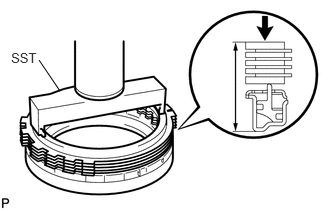
Assemble the No. 1 brake flanges, No. 1 brake discs and brake plates on the 2nd and 4th brake piston.
Using SST and a press, press the assembly with 19.6 N (2.00 kg, 4.41 lb).
- SST
- 09350-32014 (09351-32040)
Measure the assembly height.
Based on this assembly height, select a suitable hole snap ring according to the table below.
| Assembly height | Snap ring thickness | Color |
|---|---|---|
| 35.66 to 35.91 mm
(1.4039 to 1.4138 in.) |
2.25 mm (0.0886 in.) | Black |
| 35.91 to 36.16 mm
(1.4138 to 1.4236 in.) |
2.00 mm (0.0787 in.) | Brown |
| 36.16 to 36.41 mm
(1.4236 to 1.4335 in.) |
1.75 mm (0.0689 in.) | Blue |
| 36.41 to 36.66 mm
(1.4335 to 1.4433 in.) |
1.50 mm (0.0591 in.) | Silver |
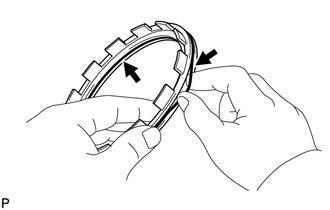
Coat 2 new O-rings with Toyota Genuine ATF Type T-IV, and install them onto the 2nd and 4th brake piston.
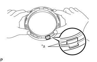
| *a | Align |
Align the claws of the 2nd and 4th brake piston and 2nd and 4th brake cylinder, and install the 2nd and 4th brake piston.
- NOTICE:
-
Do not damage the O-ring.
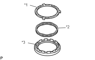
| *1 | 2nd and 4th Brake Piston Return Spring Seat |
| *2 | 2nd and 4th Brake Piston Return Spring |
| *3 | 2nd and 4th Brake Piston |
Apply Toyota Genuine ATF Type T-IV to the outer periphery of the 2nd and 4th brake cylinder.
Install the 2nd and 4th brake piston return spring seat, 2nd and 4th brake piston return spring, 2nd and 4th brake piston and 2nd and 4th brake cylinder into the transmission case.
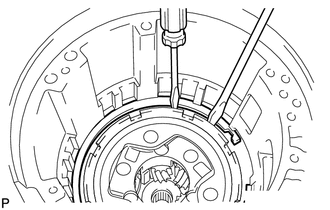
Using 2 screwdrivers, install the hole snap ring.
35681
10.INSTALL NO. 1 BRAKE DISC
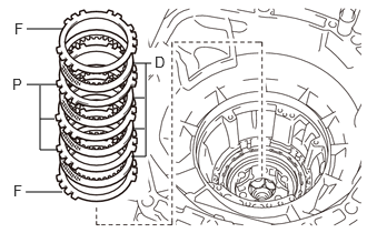
Install the 2 No. 1 brake flanges, 3 brake plates and 4 No. 1 brake discs.
- Install in order:
P = Brake plate, D = No. 1 Brake disc, F = No. 1 Brake flange
F - D - P - D - P - D - P - D - F
- HINT:
- ·
Before installing new brake discs, soak them in the Toyota Genuine ATF Type T-IV for at least 15 minutes.
·Be sure to align the cut-out section of the brake plates and brake flange when installing the brake plate.
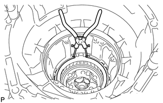
Using snap ring pliers, install the hole snap ring.
11.MEASURE BRAKE DISC END PLAY
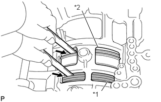
| *1 | 1st and Reverse Brake |
| *2 | 2nd and 4th Brake |
Using a feeler gauge, measure the 1st and reverse brake and 2nd and 4th brake end play.
- Standard end play:
- 1st and reverse brake:
0.65 to 1.13 mm (0.0256 to 0.0445 in.)
- 2nd and 4th brake:
1.07 to 1.52 mm (0.0421 to 0.0598 in.)
- HINT:
-
If the measured thrust clearance fails to conform to the specified value above, select a snap ring.
35709L
12.INSTALL REAR PLANETARY SUN GEAR SUB-ASSEMBLY
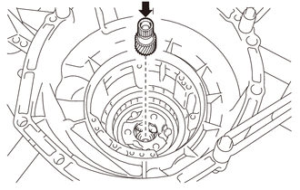
Apply Toyota Genuine ATF Type T-IV to the bush section.
Install the rear planetary sun gear sub-assembly into the transmission case.
35706U
13.INSTALL PLANETARY SUN GEAR SUB-ASSEMBLY
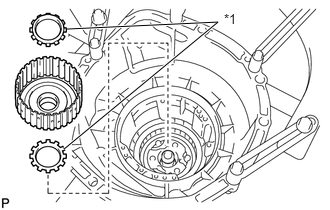
| *1 | Thrust Needle Roller Bearing |
Apply Toyota Genuine ATF Type T-IV to the bush section.
Coat the 2 thrust needle roller bearings with petroleum jelly and install them to the planetary sun gear sub-assembly.
Install the planetary sun gear sub-assembly into the transmission case.
- HINT:
-
Check the bearing installation position and direction.
35631H
14.INSTALL FORWARD CLUTCH HUB
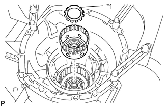
| *1 | Thrust Needle Roller Bearing |
Install the thrust needle roller bearing to the forward clutch hub.
Install the forward clutch hub to the transmission case.
- HINT:
-
Check the bearing installation position and direction.
35708J
15.INSTALL INTERMEDIATE SHAFT SUB-ASSEMBLY
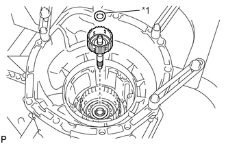
| *1 | Thrust Needle Roller Bearing |
Install the thrust needle roller bearing to the intermediate shaft sub-assembly.
Install the intermediate shaft sub-assembly to the transmission case.
- HINT:
-
Check the bearing installation position and direction.
35673
16.INSTALL REAR CLUTCH DISC
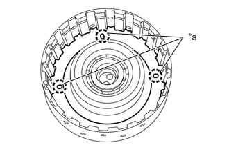
| *a | Engraved Mark |
Install the rear clutch cushion plate so that the engraved marks are visible.
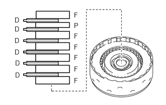
Install the 6 rear clutch flanges, 6 rear clutch discs and No. 3 clutch plate.
- Install in order:
P = No. 3 clutch plate, D = Rear clutch disc, F = Rear clutch flange
F - D - F - D - F - D - F - D - F - D - P - D - F
- HINT:
- ·
Before installing new rear clutch discs, soak them in Toyota Genuine ATF Type T-IV for at least 15 minutes.
·Be sure to align the cut-out sections of the No. 3 clutch plate and rear clutch flanges when installing them.
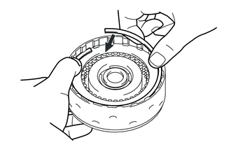
Insert the tip of the hole snap ring into the groove, and install the hole snap ring while compressing it by hand.
- NOTICE:
-
Ensure that the hole snap ring is fitted securely into the groove.
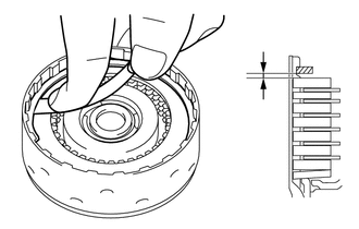
Using a feeler gauge, measure the rear clutch piston stroke.
- Standard piston stroke:
1.04 to 1.35 mm (0.0409 to 0.0532 in.)
If the result is not as specified, replace the hole snap ring with a suitable one by referring to the table below.
| Hole snap ring thickness | Part No. | Color |
|---|---|---|
| 1.50 mm (0.0591 in.) | 90045-21170 | Silver |
| 1.75 mm (0.0689 in.) | 90045-21171 | Blue |
| 2.00 mm (0.0784 in.) | 90045-21172 | Brown |
| 2.25 mm (0.0886 in.) | 90045-21173 | Black |
35633F
17.INSTALL NO. 2 CLUTCH DISC
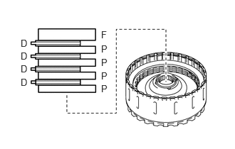
Install the 4 No. 2 clutch plates, 4 No. 2 clutch discs and forward clutch flange.
- Install in order:
P = No. 2 clutch plate, D = No. 2 clutch disc, F = Forward clutch flange
P - D - P - D - P - D - P - D - F
- HINT:
- ·
Before installing new No. 2 clutch discs, soak them in Toyota Genuine ATF Type T-IV for at least 15 minutes.
·Be sure to align the cut-out sections of the forward clutch flange and No. 2 clutch plates when installing them.
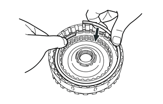
Insert the tip of the hole snap ring into the groove, and install the hole snap ring while compressing it by hand.
- NOTICE:
-
Ensure that the hole snap ring is fitted securely into the groove.
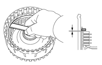
Using a feeler gauge, measure the rear clutch piston stroke.
- Standard piston stroke:
0.67 to 0.98 mm (0.0264 to 0.0386 in.)
If the result is not as specified, replace the hole snap ring with a suitable one by referring to the table below.
| Hole snap ring thickness | Part No. | Color |
|---|---|---|
| 1.50 mm (0.0591 in.) | 90045-21164 | Silver |
| 1.75 mm (0.0689 in.) | 90045-21166 | Blue |
| 2.00 mm (0.0784 in.) | 90045-21167 | Brown |
| 2.25 mm (0.0886 in.) | 90045-21168 | Black |
| 2.50 mm (0.0984 in.) | 90045-21169 | Silver |
35633B
18.INSTALL NO. 1 CLUTCH DISC
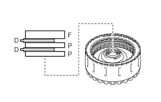
Install the 2 No. 1 clutch plates, 2 No. 1 clutch discs and reverse clutch flange.
- Install in order:
P = No. 1 clutch plate, D = No. 1 clutch disc, F = Reverse clutch flange
P - D - P - D - F
- HINT:
- ·
Before installing new clutch discs, soak them in Toyota Genuine ATF Type T-IV for at least 15 minutes.
·Be sure to align the cut-out sections of the reverse clutch flange and No. 1 clutch plates when installing them.
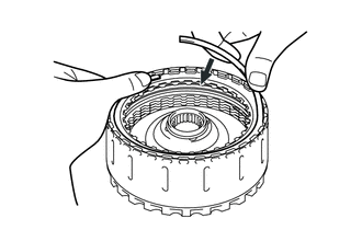
Insert the tip of the hole snap ring into the groove, and install the hole snap ring while compressing it by hand.
- NOTICE:
-
Ensure that the hole snap ring is fitted securely into the groove.
35650
19.INSTALL REAR MULTIPLE DISC CLUTCH ASSEMBLY
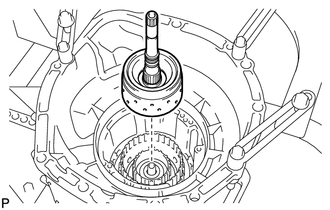
Coat 3 new input shaft oil seal rings with Toyota Genuine ATF Type T-IV, and install them to the rear multiple disc clutch assembly.
Install the rear multiple disc clutch assembly to the transmission case.
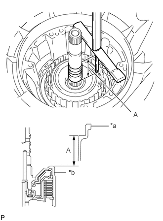
| *a | Installation Section of Front Oil Pump Body |
| *b | Rear Multiple Disc Clutch |
Using a vernier caliper, measure height A between the rear multiple disc clutch assembly and the installation section of the front oil pump body sub-assembly.
- Standard height:
Approximately 43 mm (1.69 in.)
35610
20.INSTALL FRONT MULTIPLE DISC CLUTCH ASSEMBLY
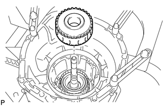
Install the front multiple disc clutch assembly into the transmission case.
Install the thrust needle roller bearing onto the front multiple disc clutch assembly.
- NOTICE:
-
Do not damage the input shaft oil seal rings of the rear multiple disc clutch assembly.
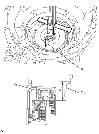
| *a | Installation Section of Front Oil Pump Body |
| *b | Front Multiple Disc Clutch |
Using a vernier caliper, measure height A, marked A, between the front multiple disc clutch assembly and the installation section of the front oil pump body sub-assembly.
- Standard height:
Approximately 43.5 mm (1.71 in.)
35301
21.INSTALL FRONT OIL PUMP BODY SUB-ASSEMBLY
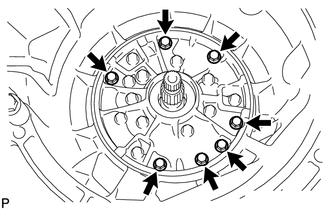
Install the front oil pump body sub-assembly into the transmission case with the 7 bolts.
- Torque:
- 8.4 N*m (85 kgf*cm, 74 in.*lbf)
- NOTICE:
-
To prevent the oil seal ring from sticking on the front multiple clutch disc drum, do not press on the front oil pump body sub-assembly hard.
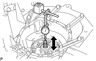
Using a dial indicator, measure the input shaft end play.
- Standard end play:
0.26 to 0.88 mm (0.0102 to 0.0346 in.)
- HINT:
-
There are 3 different thickness bearings for the end of the stator shaft.
If the thrust clearance is not within the standard range, select one of them.
- Bearing thickness:
3.41 mm (0.1343 in.)
3.81 mm (0.1500 in.)
4.21 mm (0.1657 in.)
35557
22.INSTALL PARKING LOCK PAWL
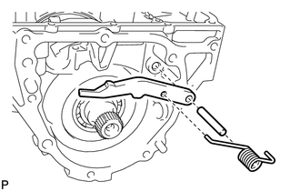
Install the parking lock pawl, parking lock pawl shaft and torsion spring.
35505
23.INSTALL MANUAL VALVE LEVER SUB-ASSEMBLY
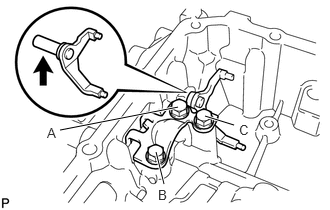
Apply Toyota Genuine ATF Type T-IV to the manual valve lever sub-assembly.
Install the parking lock pawl cam support and manual valve lever sub-assembly with the 3 bolts.
- Torque:
- 18 N*m (185 kgf*cm, 13 ft.*lbf)
- HINT:
-
Install the parking lock pawl cam support and manual valve idler shaft by slightly tightening bolt A first. Then tighten the bolts to the tightening torque in the following order.
Bolt B → C → A
35108B
24.INSTALL RADIAL BALL BEARING
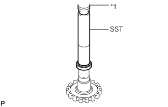
| *1 | Press |
Using SST and a press, install the radial ball bearing onto the output shaft sub-assembly.
- SST
- 09309-37010
25.INSTALL OUTPUT SHAFT SUB-ASSEMBLY
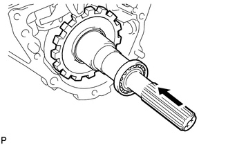
Install the output shaft sub-assembly into the transmission case.
35847C
26.INSTALL TRANSMISSION LUBE APPLY TUBE
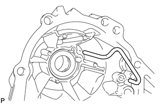
Install the transmission lube apply tube.
35108
27.INSTALL EXTENSION HOUSING SUB-ASSEMBLY
Clean the threads of the bolts and the case with a non-residue solvent.

|
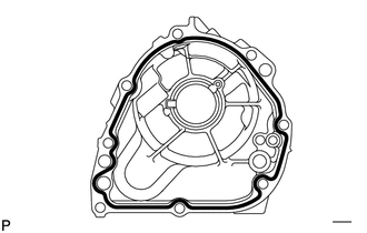
FIPG |
Apply FIPG (Diameter 1.5 to 2.5 mm (0.059 to 0.098 in.)) to the extension housing sub-assembly as shown in the illustration.
- FIPG:
Toyota Genuine Seal Packing 1281, Three Bond 1281 or equivalent
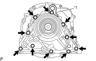
| *1 | No. 2 Engine Hanger |
Install the extension housing sub-assembly and No. 2 engine hanger with the 10 bolts.
- Torque:
- 18 N*m (185 kgf*cm, 13 ft.*lbf)
35108R
28.INSTALL AUTOMATIC TRANSMISSION EXTENSION HOUSING OIL SEAL
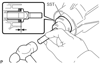
Coat a new automatic transmission extension housing oil seal lip with MP grease.
Using SST and a hammer, install the automatic transmission extension housing oil seal.
- SST
- 09325-12010
- Drive in depth:
1.0 to 2.0 mm (0.039 to 0.079 in.)
35104F
29.INSTALL TRANSMISSION CASE OIL SEAL
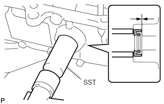
Using SST, lightly tap in a new transmission case oil seal into the transmission case.
- SST
- 09612-10093 (09612-10061)
- HINT:
- ·
When properly installed, the oil seal should be flush with the bottom of the oil seal indentation on the transmission case.
·Be careful not to damage the oil seal.
35056
30.INSTALL PARKING LOCK LEVER SUB-ASSEMBLY
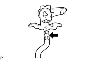
Apply Toyota Genuine ATF Type T-IV to the parking lock rod sub-assembly.
Install the parking lock rod sub-assembly into the parking lock lever sub-assembly.
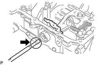
Apply Toyota Genuine ATF Type T-IV to the control shaft.
Install the control shaft into the transmission case.
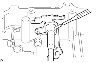
Using a pin punch and a hammer, install a new slotted spring pin.
35561
31.INSTALL MANUAL VALVE IDLER SHAFT
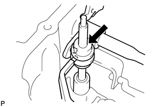
Apply Toyota Genuine ATF Type T-IV to the manual valve idler shaft.
Install the manual valve idler plug and manual valve idler shaft.
35824
32.INSTALL BRAKE CYLINDER SEAL
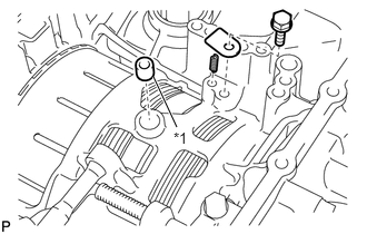
| *1 | Brake Cylinder Seal |
Coat a new brake cylinder seal with Toyota Genuine ATF Type T-IV, and install it into the transmission case.
Install the spring and plate with the bolt.
- Torque:
- 8.4 N*m (85 kgf*cm, 74 in.*lbf)
35410
33.INSTALL TRANSMISSION VALVE BODY ASSEMBLY
35409D
34.INSTALL MANUAL DETENT SPRING SUB-ASSEMBLY
35303B
35.INSTALL OIL STRAINER SUB-ASSEMBLY
35106
36.INSTALL AUTOMATIC TRANSMISSION OIL PAN SUB-ASSEMBLY
84540
37.INSTALL PARK/NEUTRAL POSITION SWITCH ASSEMBLY
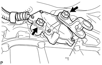
| *1 | Transmission Control Shaft Lever |
Install the park/neutral position switch assembly to the control shaft.
Temporarily install the bolt.
Temporarily install the transmission control shaft lever sub-assembly.
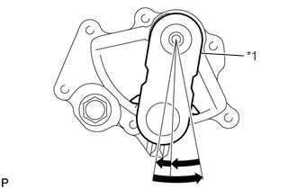
| *1 | Transmission Control Shaft Lever |
Turn the transmission control shaft lever counterclockwise until it stops, and turn it clockwise 2 notches to set it to the N position.
Remove the transmission control shaft lever.
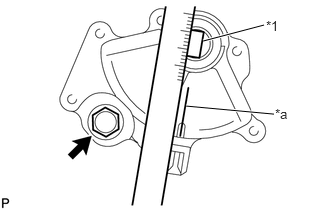
| *1 | Notch |
| *a | Neutral Basic Line |
Place a ruler tightly against the notch on the control shaft, and adjust the park/neutral position switch assembly until the neutral basic line becomes parallel with the ruler.
Hold the switch in position and tighten the bolt.
- Torque:
- 18 N*m (185 kgf*cm, 13 ft.*lbf)
35507D
38.INSTALL TRANSMISSION CONTROL SHAFT LEVER
89413E
39.INSTALL TRANSMISSION REVOLUTION SENSOR
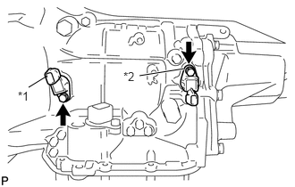
| *1 | Transmission Revolution Sensor (Input Speed Sensor) |
| *2 | Transmission Revolution Sensor (Output Speed Sensor) |
Coat 2 new O-rings with Toyota Genuine ATF Type T-IV, and install them onto the transmission revolution sensors.
Install the transmission revolution sensor (Input speed sensor) with the bolt.
- Torque:
- 8.4 N*m (85 kgf*cm, 74 in.*lbf)
Install the transmission revolution sensor (Output speed sensor) with the bolt.
- Torque:
- 8.4 N*m (85 kgf*cm, 74 in.*lbf)
35578B
40.INSTALL TRANSMISSION CONTROL CABLE BRACKET
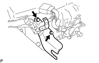
Connect the park/neutral position switch connector to the switch harness clamp.
Install the transmission control cable bracket with the 2 bolts.
- Torque:
- 18 N*m (185 kgf*cm, 13 ft.*lbf)
35108C
41.INSTALL NO. 1 BREATHER PLUG
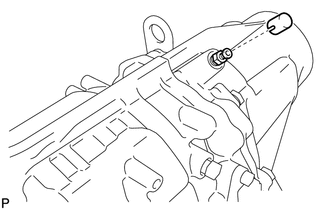
Install a new No. 1 breather plug and No. 2 breather plug.
- Torque:
- 6.4 N*m (65 kgf*cm, 57 in.*lbf)
35013
42.INSTALL TRANSMISSION OIL FILLER TUBE SUB-ASSEMBLY
35103
43.INSTALL TRANSMISSION OIL LEVEL DIPSTICK SUB-ASSEMBLY