A4Q AUTOMATIC TRANSMISSION / TRANSAXLE VALVE BODY ASSEMBLY INSTALLATION
PROCEDURE

 35824
1.INSTALL BRAKE CYLINDER SEAL
Coat a new brake cylinder seal with Toyota Genuine ATF Type T-IV, and install it into the transmission case.
35410
2.INSTALL TRANSMISSION VALVE BODY ASSEMBLY
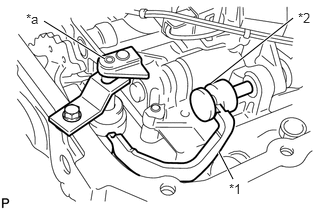
| *1 | Manual Valve Lever Sub-Assembly |
| *2 | Manual Valve |
| *a | Hole |
Install the transmission valve body assembly into the transmission case.
- HINT:
- ·
Ensure that the protrusion of the manual valve lever sub-assembly and grooved section of the manual valve are matched securely.
·Align the forward end of the manual valve idler shaft with the hole of the transmission valve body assembly.
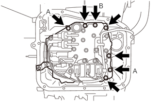
Tighten the 2 A bolts and then tighten the other 5 bolts.
- Torque:
- 8.4 N*m (85 kgf*cm, 74 in.*lbf)
- Bolt length:
65 mm (2.55 in.) for bolt B
35 mm (1.37 in.) for other bolts
Remove the SST.
- SST
- 09350-97201
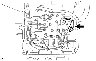
Connect the connector and clamp.
35409D
3.INSTALL MANUAL DETENT SPRING SUB-ASSEMBLY
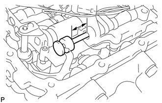
Place the manual detent spring sub-assembly on the transmission valve body assembly and manual valve.
Take the manual valve 23 mm (0.91 in.) out from the transmission valve body assembly.
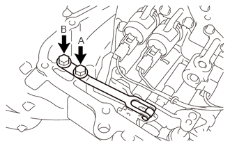
Tighten bolt A.
- Torque:
- 8.4 N*m (85 kgf*cm, 74 in.*lbf)
Tighten bolt B.
- Torque:
- 8.4 N*m (85 kgf*cm, 74 in.*lbf)
- HINT:
-
Tighten the bolts in the following order: A → B
35303B
4.INSTALL OIL STRAINER SUB-ASSEMBLY
Coat a new O-ring with Toyota Genuine ATF Type T-IV, and install it to the oil strainer sub-assembly.
Install the oil strainer sub-assembly onto the transmission valve body assembly.
33449B
5.INSTALL TRANSMISSION MAGNET
Clean the threads of the bolts and a new automatic transmission oil pan sub-assembly with a non-residue solvent.
Install the transmission magnet in the automatic transmission oil pan sub-assembly.
35106D
6.INSTALL AUTOMATIC TRANSMISSION OIL PAN SUB-ASSEMBLY
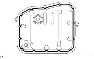

|
FIPG |
Apply FIPG (Diameter 1.5 to 2.5 mm (0.059 to 0.098 in.)) to the transmission oil pan sub-assembly as shown in the illustration.
- FIPG:
Toyota Genuine Seal Packing 1281, Three Bond 1281 or equivalent
Install the automatic transmission oil pan sub-assembly with the 14 bolts.
- Torque:
- 8.4 N*m (85 kgf*cm, 74 in.*lbf)
- HINT:
-
Tighten the bolts in diagonal order.
35103
7.INSTALL TRANSMISSION OIL LEVEL DIPSTICK SUB-ASSEMBLY
51202D
8.INSTALL FRONT LOWER SUSPENSION CROSSMEMBER SUB-ASSEMBLY
9.ADD AUTOMATIC TRANSMISSION FLUID
10.INSPECT AUTOMATIC TRANSMISSION FLUID LEVEL
11.INSPECT FOR FLUID LEAK
12.INSPECT AND ADJUST FRONT WHEEL ALIGNMENT
13.RESET MEMORY