AXLE AND DIFFERENTIAL FRONT AXLE HUB INSTALLATION
PROCEDURE

 43512D
1.INSTALL FRONT AXLE HUB BEARING LH
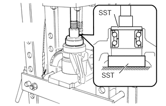
Using SST and a press, press-fit a new bearing into the steering knuckle.
- SST
- 09950-60020 (09951-00680, 09951-00780)
43502G
2.INSTALL FRONT AXLE HUB HOLE SNAP RING LH
Using snap ring pliers, install the front axle hub hole snap ring LH.
47704
3.INSTALL FRONT DISC BRAKE DUST COVER SUB-ASSEMBLY LH
Set a new brake dust cover LH to the steering knuckle.
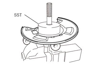
Using SST and a hammer, install the brake dust cover LH.
- SST
- 09223-56010
- NOTICE:
- ·
Uniformly press in the disc brake dust cover while sliding SST slightly.
·Press in the disc brake dust cover until it is securely seated.
43512
4.INSTALL FRONT DISC
Align the matchmarks on the axle hub and front disc, and temporarily tighten the 4 bolts.
5.INSTALL FRONT AXLE HUB WITH FRONT DISC
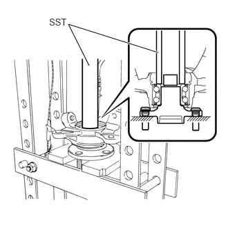
Using SST and a press, press-fit the front axle hub with the front disc into the steering knuckle.
- SST
- 09309-37010
6.INSTALL FRONT AXLE ASSEMBLY LH
Install the front axle assembly LH onto the shock absorber with the 2 bolts and 2 nuts.
- Torque:
- 128 N*m (1300 kgf*cm, 94 ft.*lbf)
- NOTICE:
-
Do not damage the lower ball joint dust cover.
- HINT:
-
Keep the bolt from rotating while turning the nut.
Install the front axle assembly onto the lower arm, and tighten it with the nut.
- Torque:
- 68 N*m (688 kgf*cm, 50 ft.*lbf)
- NOTICE:
-
Do not damage the lower ball joint dust cover.
Install a new clip.
45047
7.CONNECT TIE ROD END SUB-ASSEMBLY LH
Connect the tie rod end sub-assembly LH to the steering knuckle, and tighten it with a new nut.
8.INSTALL FRONT DISC BRAKE CALIPER ASSEMBLY LH
Install the disc brake caliper assembly LH onto the steering knuckle with the 2 bolts.
- Torque:
- 113 N*m (1150 kgf*cm, 83 ft.*lbf)
Install the flexible hose with the bolt.
- Torque:
- 17 N*m (175 kgf*cm, 13 ft.*lbf)
89543
9.INSTALL FRONT SPEED SENSOR LH (w/ ABS)
Install the speed sensor LH with the bolt.
- Torque:
- 8.4 N*m (86 kgf*cm, 74 in.*lbf)
- NOTICE:
- ·
Prevent foreign matter from attaching to the sensor tip.
·Clean the installation hole before installing the sensor.
Connect the clamp onto the shock absorber.
Install the sensor bracket onto the shock absorber with the bolt.
- Torque:
- 7.4 N*m (75 kgf*cm, 65 in.*lbf)
42601C
10.INSTALL FRONT AXLE HUB NUT
Using a 36 mm socket wrench, install a new axle hub nut and washer.
- Torque:
- 206 N*m (2100 kgf*cm, 152 ft.*lbf)
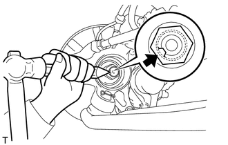
Using SST and a hammer, stake the front axle hub nut.
- SST
- 09930-00010
43514
11.INSTALL FRONT HUB GREASE CAP
- NOTICE:
-
If the hub grease cap has been damaged or deformed, replace it with a new one.
43512
12.TIGHTEN FRONT DISC
Tighten the 4 bolts.
- Torque:
- 47 N*m (475 kgf*cm, 34 ft.*lbf)
43512D
13.INSPECT FRONT AXLE HUB BEARING LH
14.INSTALL FRONT WHEEL
- Torque:
- 103 N*m (1050 kgf*cm, 76 ft.*lbf)
15. CHECK ABS SENSOR SIGNAL (w/ ABS)
16.INSPECT AND ADJUST FRONT WHEEL ALIGNMENT