INTERIOR PANELS / TRIM LOWER INSTRUMENT PANEL REMOVAL
CAUTION / NOTICE / HINT
- HINT:
-
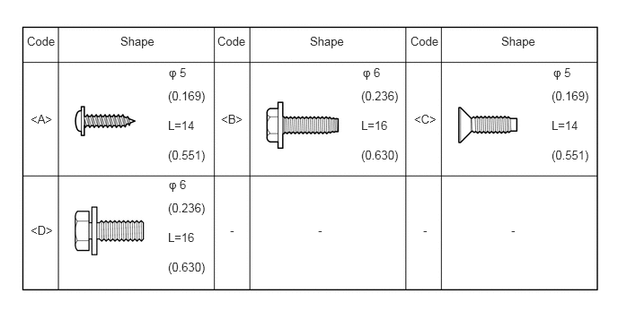
All bolts, screws and nuts relevant to installing and removing the instrument panel are shown along with their alphabet code in the table below.
PROCEDURE

 1.DISCONNECT CABLE FROM NEGATIVE BATTERY TERMINAL
- CAUTION:
-
Wait at least 90 seconds after disconnecting the cable from the negative (-) battery terminal to disable the SRS system.
- NOTICE:
-
When disconnecting the cable, some systems need to be initialized after the cable is reconnected (Click here General>INTRODUCTION>REPAIR INSTRUCTION>INITIALIZATION).
2. FRONT WHEELS FACING STRAIGHT AHEAD
55301
3.REMOVE INSTRUMENT PANEL SUB-ASSEMBLY
83100
4.REMOVE COMBINATION METER ASSEMBLY
58821A
5.REMOVE FRONT CONSOLE BOX
84140
6.REMOVE HEADLIGHT DIMMER SWITCH ASSEMBLY
84650
7.REMOVE WINDSHIELD WIPER SWITCH ASSEMBLY
(Click here Vehicle Exterior>WIPER / WASHER>WIPER SWITCH>REMOVAL)
45100
8.REMOVE STEERING WHEEL SUB-ASSEMBLY
(Click here Steering>STEERING COLUMN>STEERING WHEEL>REMOVAL)
55606
9.REMOVE NO. 1 INSTRUMENT PANEL UNDER COVER SUB-ASSEMBLY
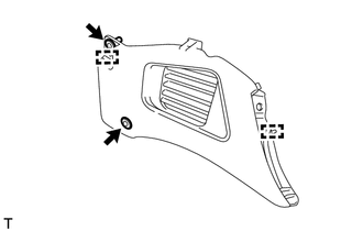
Remove the 2 clips.
Disengage the 2 guides and remove the No. 1 instrument panel under cover sub-assembly.
55608
10.REMOVE NO. 3 INSTRUMENT PANEL UNDER COVER SUB-ASSEMBLY
- HINT:
-
Use the same procedure for the No. 3 instrument panel under cover sub-assembly and No. 1 instrument panel under cover sub-assembly.
55642
11.REMOVE NO. 2 INSTRUMENT PANEL UNDER COVER
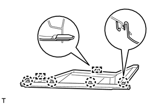
Disengage the 2 guides and the 4 claws and remove the No. 2 instrument panel under cover.
55458B
12.REMOVE INSTRUMENT LOWER COVER
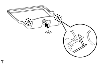
Remove the <A> screw.
Disengage the 2 claws and remove the instrument lower cover.
55420A
13.REMOVE CENTER INSTRUMENT CLUSTER FINISH PANEL ASSEMBLY
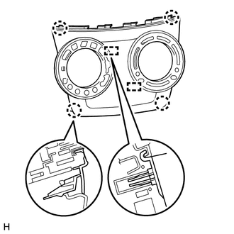
Disengage the 2 guides and the 4 claws and remove the center instrument cluster finish panel assembly.
55545
14.REMOVE FUSE BOX OPENING COVER
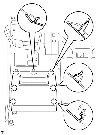
Disengage the 7 claws and remove the fuse box opening cover.
84870A
15.REMOVE OUTER MIRROR SWITCH ASSEMBLY (w/ Outer Mirror Switch)
55547
16.REMOVE REMOTE CONTROL MIRROR HOLE COVER (w/o Outer Mirror Switch)
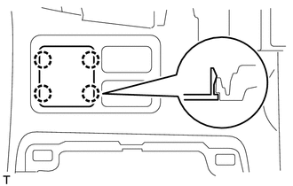
Disengage the 4 claws and remove the remote control mirror hole cover.
84790
17.REMOVE REAR WINDOW DEFOGGER SWITCH ASSEMBLY (w/ Rear Window Defogger)
55539E
18.REMOVE SPARE SWITCH HOLE COVER (w/o Rear Window Defogger)
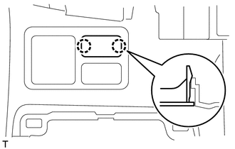
Disengage the 2 claws and remove the spare switch hole cover.
55539E
19.REMOVE SPARE SWITCH HOLE COVER
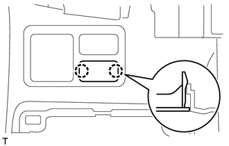
Disengage the 2 claws and remove the spare switch hole cover.
55501A
20.REMOVE GLOVE COMPARTMENT DOOR SUB-ASSEMBLY
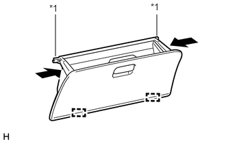
| *1 | Stopper |
Push the sections indicated by the arrows to release the 2 stoppers and open the glove compartment door sub-assembly until it is horizontal.
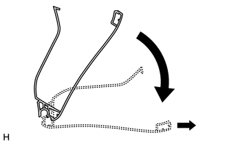
Pull the glove compartment door sub-assembly horizontally backward to disengage the 2 hinges and remove the glove compartment door sub-assembly.
- NOTICE:
-
Be sure to pull the glove compartment door sub-assembly horizontally to remove it.
55557A
21.REMOVE GLOVE COMPARTMENT DOOR CHECK CUSHION
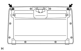
Remove the 2 glove compartment door check cushions from the glove compartment door sub-assembly.
55560A
22.REMOVE GLOVE COMPARTMENT DOOR LOCK ASSEMBLY
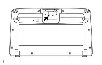
Remove the screw <C> and the glove compartment door lock assembly.
55561A
23.REMOVE GLOVE COMPARTMENT DOOR LOCK STRIKER
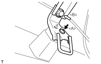

|
Bolt <B> |

|
Screw <A> |
Remove the bolt <B>.
Remove the screw <A>and the glove compartment door lock striker.
74102B
24.REMOVE FRONT ASH RECEPTACLE BOX SUB-ASSEMBLY
Remove the front ash receptacle box sub-assembly.
85500
25.REMOVE CIGARETTE LIGHTER ASSEMBLY (w/ Cigarette Lighter)
85533
26.REMOVE CIGARETTE LIGHTER INDICATOR LENS (w/ Cigarette Lighter)
55532B
27.REMOVE CIGAR LIGHTER HOLE COVER (w/o Cigarette Lighter)
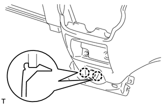
Disengage the 2 claws and remove the cigar lighter hole cover.
86316
28.REMOVE ANTENNA CABLE
81205
29.REMOVE ASH RECEPTACLE LIGHT SUB-ASSEMBLY
Remove the ash receptacle light sub-assembly.
30.REMOVE INSTRUMENT CENTER LOWER CLUSTER SEAL
Remove the instrument center lower cluster seal.
74133
31.REMOVE FRONT ASH RECEPTACLE SEAL
Remove the front ash receptacle seal.
74128
32.REMOVE FRONT ASH RECEPTACLE RETAINER SUPPORT
Remove the front ash receptacle retainer support.
55312
33.REMOVE LOWER INSTRUMENT PANEL
Disengage each connector and clamp.
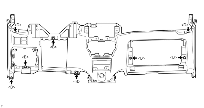
Remove the 6 <B> bolts and 2 <D> bolts, and remove the lower instrument panel.