INTERIOR PANELS / TRIM UPPER INSTRUMENT PANEL INSTALLATION
PROCEDURE

 55301
1.INSTALL INSTRUMENT PANEL SUB-ASSEMBLY
Engage the 5 guides and 8 claws to install the instrument panel sub-assembly.
- NOTICE:
-
Be careful not to damage the instrument panel sub-assembly.
Install the 4 screws.
55522B
2.INSTALL RADIO RECEIVER OPENING COVER WITH BRACKET (w/ Radio Receiver Opening Cover, for 1-piece Type)
Install the radio receiver opening cover with bracket with the 4 screws.
55522F
3.INSTALL RADIO RECEIVER OPENING COVER WITH BRACKET (w/ Radio Receiver Opening Cover, for 2-piece Type)
Install the radio receiver opening cover with bracket with the 4 screws.
86180
4.INSTALL STEREO COMPONENT TUNER ASSEMBLY WITH BRACKET (w/ USB Audio System)
86180
5.INSTALL STEREO COMPONENT TUNER ASSEMBLY WITH BRACKET (w/o USB Audio System)
55422C
6.INSTALL CENTER UPPER INSTRUMENT CLUSTER FINISH PANEL
Engage the 3 claws and 4 guides to install the center upper instrument cluster finish panel.
55061
7.INSTALL NO. 1 INSTRUMENT PANEL REGISTER SUB-ASSEMBLY
Engage the 2 claws to install the No. 1 instrument panel register sub-assembly.
55062
8.INSTALL NO. 2 INSTRUMENT PANEL REGISTER SUB-ASSEMBLY
- HINT:
-
Use the same procedure for the No. 1 instrument panel register sub-assembly.
9.INSTALL TELLTALE LIGHT ASSEMBLY
55412D
10.INSTALL CENTER INSTRUMENT CLUSTER FINISH PANEL SUB-ASSEMBLY
Engage the 2 clips and 8 claws to install the center instrument cluster finish panel sub-assembly.
73970A
11.INSTALL INSTRUMENT PANEL PASSENGER AIRBAG ASSEMBLY
55560A
12.INSTALL GLOVE COMPARTMENT DOOR LOCK ASSEMBLY
Install the glove compartment door lock assembly with the screw.
55557A
13.INSTALL GLOVE COMPARTMENT DOOR CHECK CUSHION
Install the 2 glove compartment door check cushions to the glove compartment door sub-assembly.
55501A
14.INSTALL GLOVE COMPARTMENT DOOR SUB-ASSEMBLY
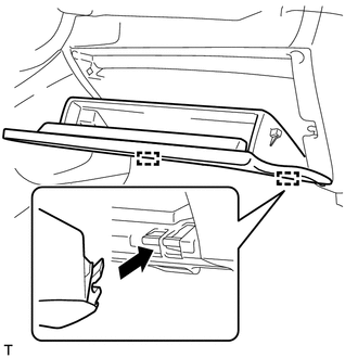
Horizontally engage the 2 hinges of the glove compartment door sub-assembly.
- NOTICE:
-
Make sure to install the glove compartment door sub-assembly horizontally.
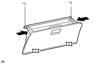
| *1 | Stopper |
Engage the 2 stoppers by pushing the sections indicated by the arrows.
55411G
15.INSTALL NO. 1 INSTRUMENT CLUSTER FINISH PANEL
86160J
16.INSTALL PILLAR SPEAKER LH (for 6 Speakers)
86160P
17.INSTALL PILLAR SPEAKER RH (for 6 Speakers)
- HINT:
-
Use the same procedure as for the LH side.
62212
18.INSTALL FRONT PILLAR GARNISH LH (for 6 Speakers)
Engage the 2 guides and 3 clips to install the front pillar garnish LH.
62211
19.INSTALL FRONT PILLAR GARNISH RH (for 6 Speakers)
- HINT:
-
Use the same procedure as for the LH side.
62212
20.INSTALL FRONT PILLAR GARNISH LH (for 4 Speakers)
- HINT:
-
Use the same procedure for the front pillar garnish LH (for 6 speakers).
62211
21.INSTALL FRONT PILLAR GARNISH RH (for 4 Speakers)
- HINT:
-
Use the same procedure for the front pillar garnish LH (for 6 speakers).
62312B
22.INSTALL FRONT DOOR OPENING TRIM WEATHERSTRIP LH
62311B
23.INSTALL FRONT DOOR OPENING TRIM WEATHERSTRIP RH
- HINT:
-
Use the same procedure as for the LH side.
62112
24.INSTALL COWL SIDE TRIM BOARD LH
Install the cowl side trim board LH with the 2 clips.
62111C
25.INSTALL COWL SIDE TRIM BOARD RH
- HINT:
-
Use the same procedure as for the LH side.
67914B
26.INSTALL FRONT DOOR SCUFF PLATE LH
67913B
27.INSTALL FRONT DOOR SCUFF PLATE RH
- HINT:
-
Use the same procedure as for the LH side.
28.CONNECT CABLE FROM NEGATIVE BATTERY TERMINAL
- Torque:
- 6.4 N*m (65 kgf*cm, 57 in.*lbf)
- NOTICE:
-
When disconnecting the cable, some systems need to be initialized after the cable is reconnected (Click here General>INTRODUCTION>REPAIR INSTRUCTION>INITIALIZATION).