HEATING / AIR CONDITIONING AIR CONDITIONING PANEL INSTALLATION
PROCEDURE

 55906A
1.INSTALL DEFROSTER DAMPER CONTROL CABLE SUB-ASSEMBLY
for RHD:
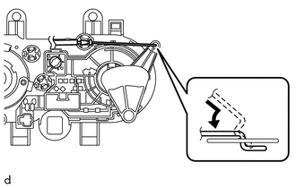
Install the defroster damper control cable sub-assembly as shown in the illustration.
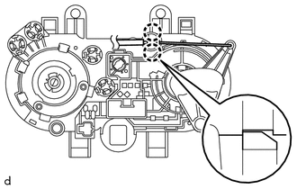
Install the outer cable into the heater control assembly as shown in the illustration.
- NOTICE:
-
Check that a clicking sound is heard.
for LHD:
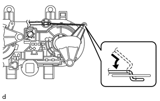
Install the defroster damper control cable sub-assembly as shown in the illustration.
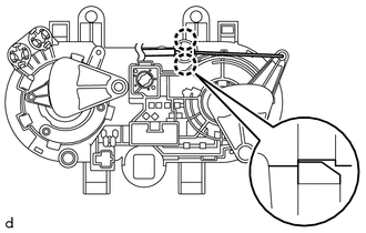
Install the outer cable into the heater control assembly as shown in the illustration.
- NOTICE:
-
Check that a clicking sound is heard.
55909A
2.INSTALL AIR MIX DAMPER CONTROL CABLE SUB-ASSEMBLY
for RHD:
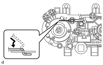
Install the air mix damper control cable sub-assembly as shown in the illustration.
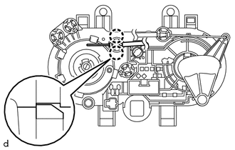
Install the outer cable into the heater control assembly as shown in the illustration.
- NOTICE:
-
Check that a clicking sound is heard.
for LHD:
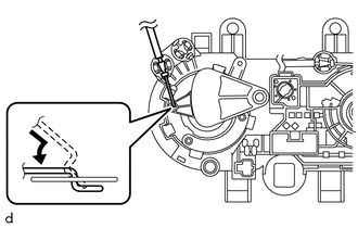
Install the air mix damper control cable sub-assembly as shown in the illustration.
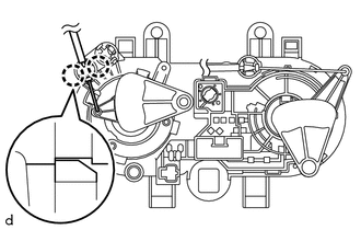
Install the outer cable into the heater control assembly as shown in the illustration.
- NOTICE:
-
Check that a clicking sound is heard.
55908A
3.INSTALL AIR INLET DAMPER CONTROL CABLE SUB-ASSEMBLY
for RHD:
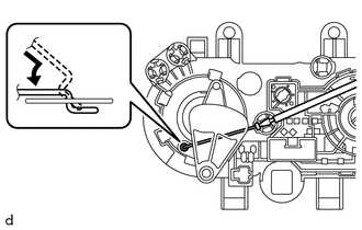
Install the air inlet damper control cable sub-assembly as shown in the illustration.
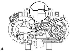
Install the outer cable into the heater control assembly as shown in the illustration.
- NOTICE:
-
Check that a clicking sound is heard.
for LHD:
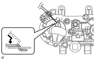
Install the air inlet damper control cable sub-assembly as shown in the illustration.
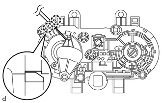
Install the outer cable into the heater control assembly as shown in the illustration.
- NOTICE:
-
Check that a clicking sound is heard.
55910R
4.INSTALL HEATER CONTROL ASSEMBLY
w/o Heater:
Connect the 2 connectors.
w/ Heater:
Connect the 2 connectors.
Engage the 2 guides.
Engage the 2 claws to install the heater control assembly.
for RHD w/o Heater:
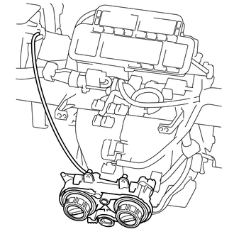
Route the air inlet damper control cable sub-assembly as shown in the illustration.
for RHD w/ Heater:
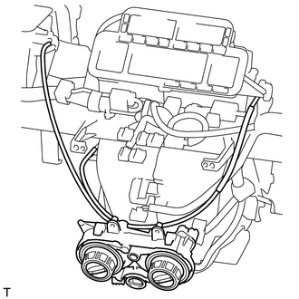
Route the 3 cables as shown in the illustration.
for LHD w/ Heater:
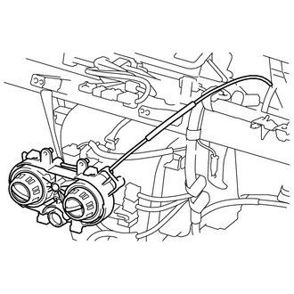
Route the air inlet damper control cable sub-assembly as shown in the illustration.
for LHD w/o Heater:
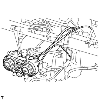
Route the 3 cables as shown in the illustration.
Connect the defroster damper control cable sub-assembly.
Set the dial knob to FACE mode.
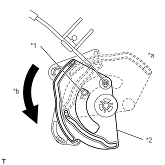
| *1 | Stopper Pin |
| *2 | Mode Selector Lever |
| *a | DEF Side |
| *b | Pull |
Push the mode selector lever against the stopper pin on DEF side, hang the inner cable on the lever and then clamp the outer cable while pulling it in the direction shown in the illustration.
Connect the air mix damper control cable sub-assembly.
Set the dial knob to MAX COOL.
Push the temperature control lever against the stopper pin on COOL side, hang the inner cable on the lever and then clamp the outer cable while pulling it in the direction shown in the illustration.
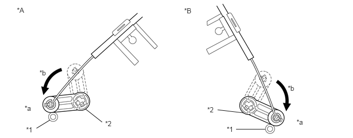
| *A | for RHD | *B | for LHD |
| *1 | Stopper Pin | *2 | Temperature Control Lever |
| *a | COOL Side | *b | Pull |
Connect the air inlet damper control cable sub-assembly.
Set the dial knob to RECIRC mode.
Push the air inlet selector lever against the stopper pin on RECIRC side, hang the inner cable on the lever and then clamp the outer cable while pulling it in the direction shown in the illustration.
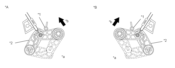
| *A | for RHD | *B | for LHD |
| *1 | Stopper Pin | *2 | Temperature Control Lever |
| *a | COOL Side | *b | Pull |
55420A
5.INSTALL CENTER INSTRUMENT CLUSTER FINISH PANEL ASSEMBLY
55412D
6.INSTALL CENTER INSTRUMENT CLUSTER FINISH PANEL SUB-ASSEMBLY
73970A
7.INSTALL INSTRUMENT PANEL PASSENGER AIRBAG ASSEMBLY
55501A
8.INSTALL GLOVE COMPARTMENT DOOR SUB-ASSEMBLY
9.CONNECT CABLE TO NEGATIVE BATTERY TERMINAL
- Torque:
- 6.4 N*m (65 kgf*cm, 57 in.*lbf)
- NOTICE:
-
When disconnecting the cable, some systems need to be initialized after the cable is reconnected (Click hereGeneral>INTRODUCTION>REPAIR INSTRUCTION>INITIALIZATION).