1NR-VE INTAKE / EXHAUST EXHAUST MANIFOLD INSTALLATION
PROCEDURE

 17168
1.INSTALL NO. 2 EXHAUST MANIFOLD HEAT INSULATOR
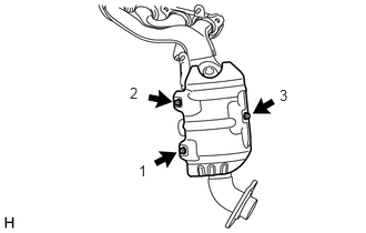
Install the No. 2 exhaust manifold heat insulator with the 3 bolts in the order shown in the illustration.
- Torque:
- 10 N*m (102 kgf*cm, 7 ft.*lbf)
17173
2.INSTALL EXHAUST MANIFOLD TO HEAD GASKET
Install a new exhaust manifold to head gasket to the cylinder head sub-assembly.
25051
3.INSTALL EXHAUST MANIFOLD CONVERTER SUB-ASSEMBLY
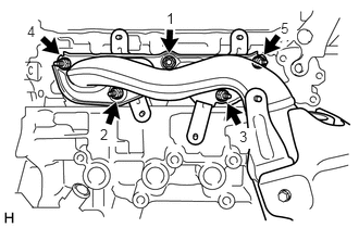
Install the exhaust manifold converter sub-assembly with the 5 new nuts in the order shown in the illustration.
- Torque:
- 40 N*m (408 kgf*cm, 30 ft.*lbf)
17167
4.INSTALL NO. 1 EXHAUST MANIFOLD HEAT INSULATOR
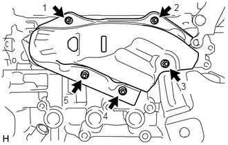
Install the No. 1 exhaust manifold heat insulator with the 5 new nuts in the order shown in the illustration.
- Torque:
- 10 N*m (102 kgf*cm, 7 ft.*lbf)
17118
5.INSTALL MANIFOLD STAY
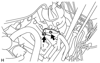
Install the manifold stay with the 2 bolts in the order shown in the illustration.
- Torque:
- 31 N*m (316 kgf*cm, 23 ft.*lbf)
45220
6.CONNECT STEERING INTERMEDIATE SHAFT ASSEMBLY (for LHD)
89465
7.INSTALL OXYGEN SENSOR
27020
8.INSTALL GENERATOR ASSEMBLY
16281
9.CONNECT NO. 4 WATER BY-PASS HOSE
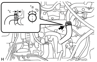
| *a | Upper Side |
| *b | 90° |
| *c | 2 to 6 mm (0.0787 to 0.2362 in.) |
Connect the No. 4 water by-pass hose with the clip as shown in the illustration.
- HINT:
-
Install the clip so that it is positioned as shown in the illustration.
17451
10.INSTALL EXHAUST PIPE GASKET
Exhaust manifold converter sub-assembly side:
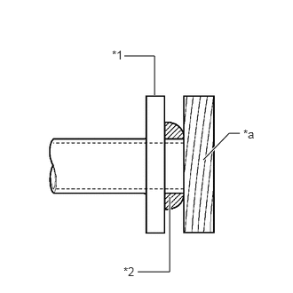
| *1 | Exhaust Manifold Converter Sub-assembly |
| *2 | Exhaust Pipe Gasket |
| *a | Wooden Block |
Using a plastic hammer and wooden block, tap in a new exhaust pipe gasket until each surface is flush with the exhaust manifold converter sub-assembly.
- NOTICE:
- ·
Be sure to install the exhaust pipe gasket in the correct direction.
·Do not reuse the exhaust pipe gasket.
·Do not damage the exhaust pipe gasket.
·Do not push in the exhaust pipe gasket by using the exhaust pipes when connecting it.
Tail exhaust pipe assembly side:
Install a new exhaust pipe gasket to the front exhaust pipe assembly.
17410
11.SET FRONT EXHAUST PIPE ASSEMBLY
58151A
12.INSTALL NO. 1 FLOOR HEAT INSULATOR
17410
13.INSTALL FRONT EXHAUST PIPE ASSEMBLY
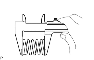
Using a vernier caliper, measure the free length of the compression springs.
| Minimum | 41.1 mm (1.62 in.) |
If the free length is less than the minimum, replace the compression spring.
Connect the front exhaust pipe assembly to the No. 2 exhaust pipe support.
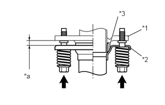
| *1 | Exhaust Manifold Converter Sub-assembly |
| *2 | Front Exhaust Pipe Assembly |
| *3 | Exhaust Pipe Gasket |
| *a | Space between flanges: 8.5 mm (0.335 in.) |
Install the front exhaust pipe assembly with the 4 bolts, 2 new nuts and 2 compression springs.
- Torque:
- Exhaust manifold converter sub-assembly side : 46.5 N*m (474 kgf*cm, 34 ft.*lbf)
- Tail exhaust pipe assembly side : 19 N*m (194 kgf*cm, 14 ft.*lbf)
- HINT:
-
After installation, check that the space between the flanges of the exhaust manifold converter sub-assembly and front exhaust pipe assembly are consistent front-to-rear and left-to-right.
14.ADD ENGINE COOLANT
15.INSPECT FOR COOLANT LEAK
16.INSPECT FOR EXHAUST GAS LEAK
51473A
17.INSTALL ENGINE SIDE COVER SUB-ASSEMBLY RH