BRAKE CONTROL / DYNAMIC CONTROL SYSTEMS ANTI-LOCK BRAKE SYSTEM DIAGNOSIS SYSTEM
DESCRIPTION
When troubleshooting a vehicle with the diagnosis system, the only difference from the usual troubleshooting procedure is connecting the GTS or Techstream to the vehicle and reading various data output from the skid control ECU (brake actuator assembly).
The skid control ECU (brake actuator assembly) stores DTCs when the ECU detects a malfunction in the ECU itself or in its circuits.
To check the DTCs, connect the GTS or Techstream to the DLC3 of the vehicle. The GTS or Techstream enables you to clear the DTCs, activate various actuators, and check the freeze frame data and Data List.
Check the battery voltage.
- Standard voltage:
11 to 14 V
If the voltage is below 11 V, recharge the battery before proceeding to the next step.
DIAGNOSIS
If the skid control ECU (brake actuator assembly) detects a malfunction, the ABS warning light and brake warning light will come on in order to warn the driver.
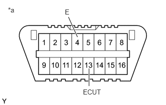
| *a | Front view of DLC3 |
DTCs are simultaneously stored in memory. Output DTCs can be read by connecting SST to terminals 13 (ECUT) and 4 (E) of the DLC3 and observing the blinking pattern of the ABS warning light or by connecting the GTS or Techstream.
Click hereBrake>BRAKE CONTROL / DYNAMIC CONTROL SYSTEMS>ANTI-LOCK BRAKE SYSTEM>DTC CHECK / CLEAR
This system has a test mode (signal check) function.
Click hereBrake>BRAKE CONTROL / DYNAMIC CONTROL SYSTEMS>ANTI-LOCK BRAKE SYSTEM>TEST MODE PROCEDURE
WARNING LIGHT INITIAL CHECK
When the ignition switch is turned to ON, check that the ABS warning light and brake warning light come on for approximately 3 seconds.
- HINT:
-
If the warning light check result is not normal, proceed to troubleshooting for the ABS warning light and brake warning light circuits.
If an indicator remains on or does not come on, proceed to troubleshooting for the light circuits listed below.
| Trouble Area | See procedure |
|---|---|
| ABS warning light circuit (Remains on) | ( ) |
| ABS warning light circuit (Does not come on) | ()
|
| Brake warning light circuit (Remains on) | ()
|
| Brake warning light circuit (Does not come on) | ()
|