A4R AUTOMATIC TRANSMISSION / TRANSAXLE AUTOMATIC TRANSMISSION SYSTEM P0705 Transmission Range Sensor Circuit Malfunction
DESCRIPTION
The Park/Neutral position switch detects the shift lever position and sends the signals to the ECM.
| DTC No. | Detection Item | DTC Detection Condition | Trouble Area | MIL | Warning Indicate | Memory | Note |
|---|---|---|---|---|---|---|---|
| P0705 | Transmission Range Sensor Circuit Malfunction | 1. Diagnosis Condition 2. Malfunction Status 3. Malfunction Time 4. Other
1.
Ignition switch ON 2.
When the condition that the signal is not input is detected for more than a specified period. 3.
1 seconds 4.
1-trip detection logic |
·
Open in Park/Neutral position switch circuit ·
Park/Neutral position switch assembly ·
ECM |
Comes on | Blinks | DTC not stored | When terminals ECUT and E of the DLC3 are connected, warning indicate blinks. |
| DTC No. | Detection Item | DTC Detection Condition | Trouble Area | MIL | Warning Indicate | Memory | Note |
|---|---|---|---|---|---|---|---|
| P0705 | Transmission Range Sensor Circuit Malfunction | 1. Diagnosis Condition 2. Malfunction Status 3. Malfunction Time 4. Other
1.
Ignition switch ON 2.
2 or more switches are ON simultaneously for more than a specified period for P, R, N, D, 3 and 2 positions. 3.
2 seconds 4.
1-trip detection logic |
·
Open in Park/Neutral position switch circuit ·
Park/Neutral position switch assembly ·
ECM |
Comes on | Blinks | DTC stored | - |
MIL:"Comes on" means the MIL (Malfunction Indicator Light) illuminates.
Memory:"DTC stored" means the ECM stores the trouble code if the ECU detects the DTC detection condition.
WIRING DIAGRAM
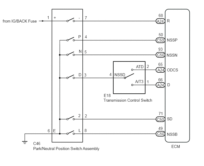
PROCEDURE
Disconnect the C46 park/neutral position switch connector.
Measure the resistance according to the value(s) in the table below.
- Standard Resistance:
Tester Connection Condition Specified Condition C46-6 (E) - Body ground Always Below 1 Ω
- Result:
Proceed to OK NG
OK
NG
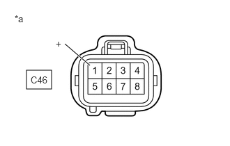
| *a | Front view of wire harness connector
(to Park/Neutral Position Switch) |
Turn the ignition switch to ON.
Measure the voltage according to the value(s) in the table below.
- Standard Voltage:
Tester Connection Switch Condition Specified Condition C46-1 (+) - Body ground Ignition switch ON 11 to 14 V Ignition switch off Below 1 V
- Result:
Proceed to OK NG
OK
NG
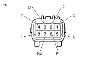
| *a | Component without harness connected
(Park/Neutral Position Switch) |
Measure the resistance according to the value(s) in the table below.
- Standard Resistance:
Tester Connection Switch Condition Specified Condition 4 (P) - 6 (E) Shift lever in P Below 1 Ω Shift lever not in P 10 kΩ or higher 1 (R) - 7 (RB) Shift lever in R Below 1 Ω Shift lever not in R 10 kΩ or higher 5 (N) - 6 (E) Shift lever in N Below 1 Ω Shift lever not in N 10 kΩ or higher 3 (D) - 6 (E) Shift lever in D Below 1 Ω Shift lever not in D 10 kΩ or higher 2 (2) - 6 (E) Shift lever in 2 Below 1 Ω Shift lever not in 2 10 kΩ or higher 8 (L) - 6 (E) Shift lever in L Below 1 Ω Shift lever not in L 10 kΩ or higher
Reconnect the C46 park/neutral position switch connector.
- Result:
Proceed to OK NG
OK
NG
Disconnect the E18 transmission control switch connector.
Measure the resistance according to the value(s) in the table below.
- Standard Resistance:
Tester Connection Switch Condition Specified Condition E18-4 (NSSD) - Body ground Shift lever in D Below 1 Ω Shift lever not in D 10 kΩ or higher
- Result:
Proceed to OK NG
OK
NG
Disconnect the A24 ECM connectors.
Measure the resistance according to the value(s) in the table below.
- Standard Resistance:
Tester Connection Condition Specified Condition A24-66 (D) - E18-1 (A/T3) Always Below 1 Ω A24-65 (ODCS) - E18-2 (ATD) Always Below 1 Ω
Reconnect the A24 ECM connectors.
- Result:
Proceed to OK NG
OK
NG
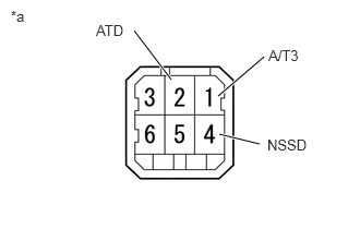
| *a | Component without harness connected
(Transmission Control Switch) |
Measure the resistance according to the value(s) in the table below.
- Standard Resistance:
Tester Connection Switch Condition Specified Condition 1 (A/T3) - 4 (NSSD) Shift lever in D 10 kΩ or higher Shift lever in 3 Below 1 Ω 2 (ATD) - 4 (NSSD) Shift lever in D Below 1 Ω Shift lever in 3 10 kΩ or higher
Reconnect the E18 transmission control switch connector.
- Result:
Proceed to OK NG
OK
NG
Disconnect the C50 ECM connector.
Measure the resistance according to the value(s) in the table below.
- Standard Resistance:
Tester Connection Switch Condition Specified Condition C50-50 (NSSP) - Body ground Shift lever in P Below 1 Ω Shift lever not in P 10 kΩ or higher C50-93 (NSSN) - Body ground Shift lever in N Below 1 Ω Shift lever not in N 10 kΩ or higher C50-71 (SD) - Body ground Shift lever in 2 Below 1 Ω Shift lever not in 2 10 kΩ or higher C50-49 (NSSB) - Body ground Shift lever in L Below 1 Ω Shift lever not in L 10 kΩ or higher
Reconnect the C50 ECM connector.
Disconnect the A24 ECM connector.
Turn the ignition switch to ON
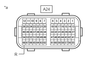
| *a | Front view of wire harness connector
(to ECM) |
Measure the voltage according to the value(s) in the table below.
- Standard Voltage:
Tester Connection Switch Condition Specified Condition A24-68 (R) - Body ground Shift lever in R 11 to 14 V Shift lever not in R Below 1 V
Reconnect the A24 ECM connector.
- Result:
Result Proceed to OK (for 1NR-VE) A OK (for 2NR-VE) B NG C
A
B
C