Home › Vehicle Interior › DOOR LOCK › POWER DOOR LOCK CONTROL SYSTEM › from 2015.08
RM19Y0E _58 Vehicle Interior _003005 DOOR LOCK _0015186 POWER DOOR LOCK CONTROL SYSTEM J

DOOR LOCK  POWER DOOR LOCK CONTROL SYSTEM  All Doors LOCK / UNLOCK Functions do not Operate Via Driver Side Door Key Cylinder  


DESCRIPTION

The main body ECU (fuse block assembly) receives switch signals from the driver side door key cylinder lock or unlock switch signals from the front door lock assembly LH*1 or RH*2. The main body ECU (fuse block assembly) activates the door lock motor on each door according to these signals.

*1: for LHD

*2: for RHD


WIRING DIAGRAM
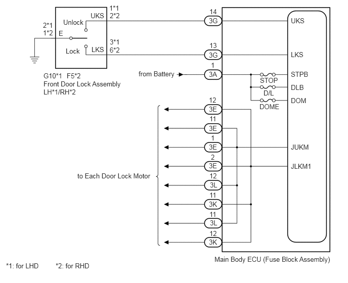
B413863E02
5.99,0.344 6.51,0.667 0.521,0.323 10 false UKS 1.865,0.24 2.385,0.563 0.521,0.323 10 false UKS 1.885,0.938 2.406,1.26 0.521,0.323 10 false LKS 5.99,1.042 6.51,1.365 0.521,0.323 10 false LKS 4.313,0.156 4.833,0.479 0.521,0.323 10 false 14 4.313,0.854 4.833,1.177 0.521,0.323 10 false 13 2.25,0.083 2.771,0.406 0.521,0.323 10 false 1*1 2.26,0.948 2.781,1.271 0.521,0.323 10 false 6*2 0.885,0.594 1.406,0.917 0.521,0.323 10 false 1*2 1.208,0.604 1.729,0.927 0.521,0.323 10 false E 0.896,1.479 1.417,1.802 0.521,0.323 10 false G10*1 4.302,0.344 4.823,0.667 0.521,0.323 10 false 3G 0.896,1.646 2.563,2.49 1.667,0.844 10 false Front Door Lock Assembly LH*1/RH*2 4.417,5.26 7.156,5.688 2.74,0.427 10 false Main Body ECU (Fuse Block Assembly) 1.375,1.479 1.896,1.802 0.521,0.323 10 false F5*2 0.125,5.396 1.094,5.76 0.969,0.365 10 false *1: for LHD 1.146,5.396 2.115,5.76 0.969,0.365 10 false *2: for RHD 4.302,1.052 4.823,1.375 0.521,0.323 10 false 3G 4.302,1.448 4.823,1.771 0.521,0.323 10 false 3A 4.302,2.167 4.823,2.49 0.521,0.323 10 false 3E 4.302,2.563 4.823,2.885 0.521,0.323 10 false 3E 4.302,2.948 4.823,3.271 0.521,0.323 10 false 3E 4.302,3.333 4.823,3.656 0.521,0.323 10 false 3E 4.323,3.729 4.844,4.052 0.521,0.323 10 false 3L 4.302,4.125 4.823,4.448 0.521,0.323 10 false 3K 4.323,4.51 4.844,4.833 0.521,0.323 10 false 3L 4.302,4.906 4.823,5.229 0.521,0.323 10 false 3K 1.594,3.542 3.469,3.99 1.875,0.448 10 false to Each Door Lock Motor 2.854,1.438 3.927,1.813 1.073,0.375 10 false from Battery 4.344,1.26 4.865,1.583 0.521,0.323 10 false 1 4.302,1.979 4.823,2.302 0.521,0.323 10 false 12 4.313,2.365 4.833,2.688 0.521,0.323 10 false 11 4.344,2.76 4.865,3.083 0.521,0.323 10 false 1 4.344,3.156 4.865,3.479 0.521,0.323 10 false 2 4.313,3.542 4.833,3.865 0.521,0.323 10 false 12 4.313,3.938 4.833,4.26 0.521,0.323 10 false 11 4.313,4.333 4.833,4.656 0.521,0.323 10 false 11 4.313,4.729 4.833,5.052 0.521,0.323 10 false 12 2.26,0.24 2.781,0.563 0.521,0.323 10 false 2*2 2.26,0.781 2.781,1.104 0.521,0.323 10 false 3*1 0.885,0.438 1.406,0.76 0.521,0.323 10 false 2*1 1.354,0.969 2.031,1.302 0.677,0.333 10 false Lock 1.302,0.375 1.979,0.708 0.677,0.333 10 false Unlock 5.99,2.948 6.51,3.271 0.521,0.323 10 false JUKM 5.99,3.344 6.51,3.667 0.521,0.323 10 false JLKM1 5.99,1.448 6.51,1.771 0.521,0.323 10 false STPB 5.99,1.719 6.51,2.042 0.521,0.323 10 false DLB 5.99,1.99 6.51,2.313 0.521,0.323 10 false DOM 5.354,1.573 5.875,1.896 0.521,0.323 10 false STOP 5.427,1.833 5.948,2.156 0.521,0.323 10 false D/L 5.344,2.115 5.865,2.438 0.521,0.323 10 false DOME

PROCEDURE

1.READ VALUE USING GTS OR TECHSTREAM (LOCK SW, UNLOCK SW)
a.

Connect the GTS or Techstream to the DLC3.


b.

Turn the ignition switch ON.


c.

Turn the GTS or Techstream on.


d.

Enter the following menus: Body Electrical / Body / Data List.


e.

Read the Data List according to the display on the GTS or Techstream.

Body Electrical > Body > Data List
Tester Display Measurement Item Range Normal Condition Diagnostic Note
Lock SW Driver side door lock position signal OFF or ON OFF: Driver side door unlocked
ON: Driver side door locked
-
Unlock SW Driver side door unlock position signal OFF or ON OFF: Driver side door locked
ON: Driver side door unlocked
-

OK:

On the GTS or Techstream screen, the display changes between ON and OFF as shown in the table above.


Result:
Proceed to
OK
NG


OK

2.PERFORM ACTIVE TEST USING GTS OR TECHSTREAM (DOOR LOCK MOTOR)

NG

3.INSPECT FRONT DOOR LOCK ASSEMBLY
2.PERFORM ACTIVE TEST USING GTS OR TECHSTREAM (DOOR LOCK MOTOR)
a.

Connect the GTS or Techstream to the DLC3.


b.

Turn the ignition switch to ON.


c.

Turn the GTS or Techstream on.


d.

Enter the following menus: Body Electrical / Body / Active Test.


e.

Perform the Active Test according to the display on the GTS or Techstream.

Body Electrical > Body > Active Test
Tester Display Measurement Item Control Range Diagnostic Note
Door lock motor Door lock motor Unlock/Lock/Reverse -

OK:

The door lock motors operate normally.


Result:
Result Proceed to
OK (for LHD) A
OK (for RHD) B
NG C


A

REPLACE MAIN BODY ECU (FUSE BLOCK ASSEMBLY)

B

REPLACE MAIN BODY ECU (FUSE BLOCK ASSEMBLY)

C

5.CHECK HARNESS AND CONNECTOR (BATTERY - MAIN BODY ECU (FUSE BLOCK ASSEMBLY))
3.INSPECT FRONT DOOR LOCK ASSEMBLY
a.

for LHD

i.

Remove the front door lock assembly LH.

Click hereVehicle Interior>DOOR LOCK>FRONT DOOR LOCK>REMOVAL


ii.

Inspect the front door lock assembly LH.

Click hereVehicle Interior>DOOR LOCK>FRONT DOOR LOCK>INSPECTION


b.

for RHD

i.

Remove the front door lock assembly RH.

Click hereVehicle Interior>DOOR LOCK>FRONT DOOR LOCK>REMOVAL


ii.

Inspect the front door lock assembly RH.

Click hereVehicle Interior>DOOR LOCK>FRONT DOOR LOCK>INSPECTION


Result:
Proceed to
OK
NG


OK

4.CHECK HARNESS AND CONNECTOR (MAIN BODY ECU (FUSE BLOCK ASSEMBLY) - FRONT DOOR LOCK ASSEMBLY)

NG

REPLACE FRONT DOOR LOCK ASSEMBLY

4.CHECK HARNESS AND CONNECTOR (MAIN BODY ECU (FUSE BLOCK ASSEMBLY) - FRONT DOOR LOCK ASSEMBLY)
a.

Disconnect the 3G main body ECU (fuse block assembly) connector.

b.

Disconnect the G10*1 or F5*2 front door lock assembly connector.


c.

Measure the resistance according to the value(s) in the table below.

Standard Resistance:
for LHD
Tester Connection Condition Specified Condition
3G-13 - G10-3 (LKS) Always Below 1 Ω
3G-14 - G10-1 (UKS) Always Below 1 Ω
G10-2 (E) - Body ground Always Below 1 Ω
3G-13 or G10-3 (LKS) - Body ground Always 10 kΩ or higher
3G-14 or G10-1 (UKS) - Body ground Always 10 kΩ or higher

for RHD
Tester Connection Condition Specified Condition
3G-13 - F5-6 (LKS) Always Below 1 Ω
3G-14 - F5-2 (UKS) Always Below 1 Ω
F5-1 (E) - Body ground Always Below 1 Ω
3G-13 or F5-6 (LKS) - Body ground Always 10 kΩ or higher
3G-14 or F5-2 (UKS) - Body ground Always 10 kΩ or higher


Result:
Result Proceed to
OK (for LHD) A
OK (for RHD) B
NG C


A

REPLACE MAIN BODY ECU (FUSE BLOCK ASSEMBLY)

B

REPLACE MAIN BODY ECU (FUSE BLOCK ASSEMBLY)

C

REPAIR OR REPLACE HARNESS OR CONNECTOR

5.CHECK HARNESS AND CONNECTOR (BATTERY - MAIN BODY ECU (FUSE BLOCK ASSEMBLY))
a.

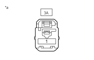
Disconnect the 3A main body ECU (fuse block assembly) connector.


b.
B413862C01
1.49,0.323 1.906,0.573 0.417,0.25 0.177,0.188 0.625,0.49 0.448,0.302 10 false *a 1.604,0.385 2.052,0.688 0.448,0.302 10 false 3A
*a Front view of wire harness connector
(to Main Body ECU (Fuse Block Assembly) connector)


Measure the voltage according to the value(s) in the table below.

Standard Voltage:
Tester Connection Condition Specified Condition
3A-1 - Body ground Always 11 to 14 V


Result:
Result Proceed to
OK (for LHD) A
OK (for RHD) B
NG C


A

REPLACE MAIN BODY ECU (FUSE BLOCK ASSEMBLY)

B

REPLACE MAIN BODY ECU (FUSE BLOCK ASSEMBLY)

C

REPAIR OR REPLACE HARNESS OR CONNECTOR