A4R AUTOMATIC TRANSMISSION / TRANSAXLE AUTOMATIC TRANSMISSION UNIT DISASSEMBLY
PROCEDURE

 35108C
1.REMOVE AUTOMATIC EXTENSION HOUSING PLUG
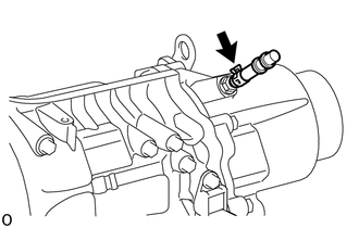
Loosen the hose clamp and remove the automatic extension housing plug.
35578B
2.REMOVE TRANSMISSION CONTROL CABLE BRACKET
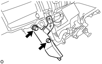
Remove the 2 bolts and transmission control cable bracket.
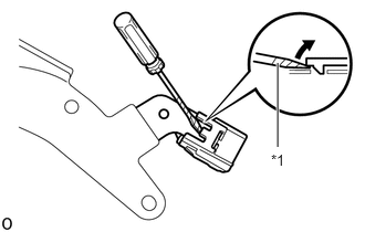
| *1 | Protective Tape |
Using a screwdriver, disconnect the connector of the park/neutral position switch from the switch harness clamp.
- HINT:
-
Tape up the screwdriver tip before use.
89413B
3.REMOVE TRANSMISSION REVOLUTION SENSOR
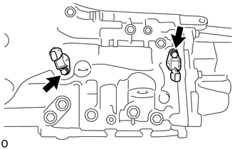
Remove the bolt and the transmission revolution sensor (Output speed sensor).
Remove the bolt and the transmission revolution sensor (Input speed sensor).
Remove the 2 O-ring from the transmission revolution sensors.
35507E
4.REMOVE TRANSMISSION CONTROL SHAFT LEVER
84540
5.REMOVE PARK/NEUTRAL POSITION SWITCH ASSEMBLY
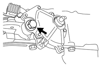
Remove the bolt and pull out the park/neutral position switch assembly.
- HINT:
-
Make sure that the manual valve lever sub-assembly has not been rotated prior to installing the park/neutral position switch assembly as the detent spring may become detached from the manual valve lever sub-assembly.
35000
6.FIX AUTOMATIC TRANSMISSION ASSEMBLY
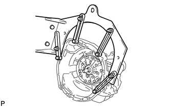
Install the automatic transmission assembly on the overhaul attachment.
35106
7.REMOVE AUTOMATIC TRANSMISSION OIL PAN SUB-ASSEMBLY
33449B
8.REMOVE TRANSMISSION MAGNET
35303
9.REMOVE OIL STRAINER SUB-ASSEMBLY
35409D
10.REMOVE MANUAL DETENT SPRING SUB-ASSEMBLY
35410
11.REMOVE TRANSMISSION VALVE BODY ASSEMBLY
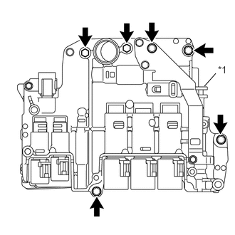
| *1 | Manual Valve |
Uniformly loosen the 6 bolts and remove the transmission valve body assembly.
- NOTICE:
-
Make sure not to drop the manual valve.
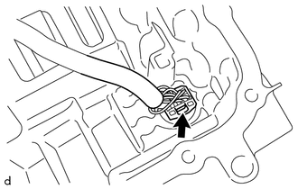
Disconnect the connector of the solenoid wire assembly.
- NOTICE:
-
Never pull out the wire itself directly when disconnecting the connector.
35824
12.REMOVE BRAKE CYLINDER SEAL
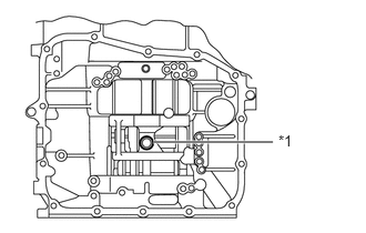
| *1 | Brake Cylinder Seal |
Remove the brake cylinder seal.
35056
13.REMOVE PARKING LOCK WITH ROLLER LEVER SUB-ASSEMBLY
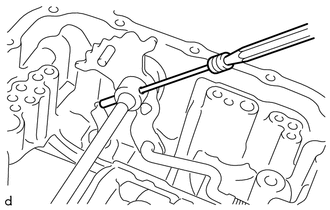
Using a pin punch and a hammer, remove the slotted spring pin.
- NOTICE:
-
When removing the pin, do not drop it into the transmission case.
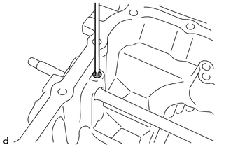
Using a 3 mm hexagon wrench, remove the set bolt.
Remove the control shaft.
Remove the parking lock lever sub-assembly and parking lock rod sub-assembly.
33111Q
14.REMOVE TRANSMISSION CASE OIL SEAL
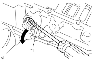
| *1 | Protective Tape |
Using a screwdriver, remove the transmission case oil seal from the transmission case.
- HINT:
-
Tape up the screwdriver tip before use.
35108R
15.REMOVE AUTOMATIC TRANSMISSION EXTENSION HOUSING OIL SEAL
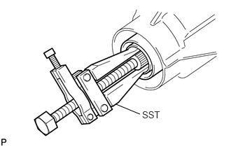
Using SST, remove the automatic transmission extension housing oil seal.
- SST
- 09308-10010
35108
16.REMOVE EXTENSION (ATM) HOUSING SUB-ASSEMBLY
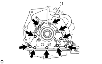
| *1 | No. 2 Engine Hanger |
Remove the 10 bolts and No. 2 engine hanger.
- HINT:
-
Be sure to remove the bolts evenly, removing opposing bolts in sequence.
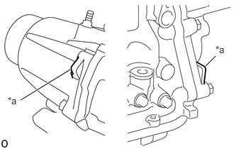
| *a | Rib |
Using a plastic hammer, lightly tap the 2 ribs on the extension (ATM) housing sub-assembly to remove it.
35073
17.REMOVE OUTPUT SHAFT SUB-ASSEMBLY
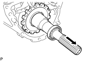
Remove the output shaft sub-assembly.
35771D
18.REMOVE OUTPUT SHAFT BALL BEARING
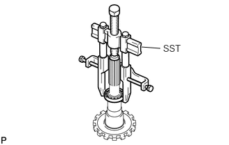
Using SST, remove the output shaft ball bearing.
- SST
- 09950-40011 (09951-04010, 09952-04010, 09953-04030, 09954-04020, 09955-04061, 09957-04010, 09958-04011)
- NOTICE:
-
Before using SST (center bolt), apply hypoid gear oil to its threads and tip.
35557
19.REMOVE PARKING LOCK PAWL
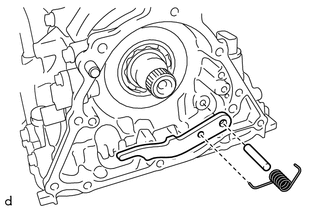
Remove the torsion spring, parking lock pawl shaft and parking lock pawl.
35595
20.REMOVE PARKING LOCK PAWL BRACKET
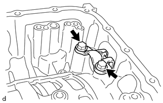
Remove the 2 bolts and parking lock pawl bracket.
35301
21.INSPECT FRONT OIL PUMP BODY SUB-ASSEMBLY
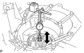
Using a dial indicator, measure the input shaft end play.
- Standard end play:
0.26 to 0.88 mm (0.0102 to 0.0346 in.)
35301
22.REMOVE FRONT OIL PUMP BODY SUB-ASSEMBLY
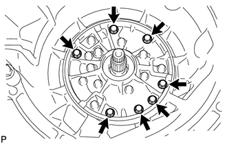
Remove the 7 bolts.
- HINT:
-
Be sure to remove the bolts evenly, removing opposing bolts in sequence.
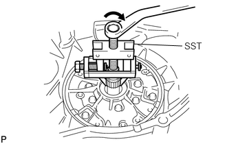
Using SST, remove the front oil pump body sub-assembly.
- SST
- 09820-00021
35610
23.REMOVE FRONT MULTIPLE DISC CLUTCH ASSEMBLY
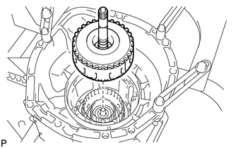
Remove the front multiple disc clutch assembly with rear multiple disc clutch assembly.
35650
24.REMOVE REAR MULTIPLE DISC CLUTCH ASSEMBLY
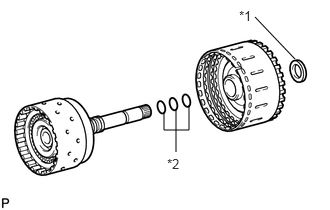
| *1 | Thrust Needle Roller Bearing |
| *2 | Input Shaft Oil Seal Ring |
Remove the rear multiple disc clutch assembly from the front multiple disc clutch assembly.
Remove the thrust needle roller bearing from the front multiple disc clutch assembly.
Remove the 3 input shaft oil seal rings from the rear multiple disc clutch assembly.
35610
25.INSPECT FRONT MULTIPLE DISC CLUTCH ASSEMBLY
35633B
26.REMOVE FORWARD MULTIPLE DISC CLUTCH CLUTCH DISC
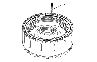
| *1 | Protective Tape |
Using a screwdriver, remove the hole snap ring.
- HINT:
-
Tape up the screwdriver tip before use.
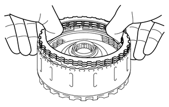
Remove the reverse clutch flange, 2 forward multiple disc clutch clutch discs and 2 No. 1 clutch plates.
35633B
27.INSPECT FORWARD MULTIPLE DISC CLUTCH CLUTCH DISC
35633F
28.REMOVE FRONT CLUTCH CLUTCH DISC
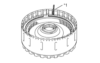
| *1 | Protective Tape |
Using a screwdriver, remove the hole snap ring.
- HINT:
-
Tape up the screwdriver tip before use.
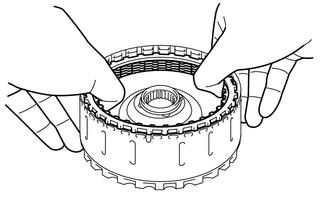
Remove the forward clutch flange, 4 front clutch clutch discs and 4 No. 2 clutch plates.
35633F
29.INSPECT FRONT CLUTCH CLUTCH DISC
35650
30.INSPECT REAR MULTIPLE DISC CLUTCH ASSEMBLY
35673
31.REMOVE REAR CLUTCH DISC
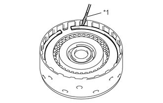
| *1 | Protective Tape |
Using a screwdriver, remove the hole snap ring.
- HINT:
-
Tape up the screwdriver tip before use.
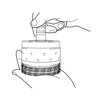
Remove the 2 rear clutch flanges, 8 rear clutch discs and 7 No. 3 clutch plates.
35673
32.INSPECT REAR CLUTCH DISC
35708
33.REMOVE INTERMEDIATE SHAFT SUB-ASSEMBLY
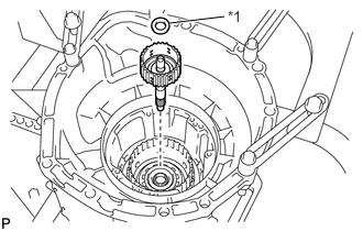
| *1 | Thrust Needle Roller Bearing |
Remove the intermediate shaft sub-assembly.
Remove the thrust needle roller bearing from the intermediate shaft sub-assembly.
35631J
34.REMOVE NO. 1 FORWARD CLUTCH HUB
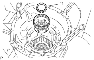
| *1 | Thrust Needle Roller Bearing |
Remove the No. 1 forward clutch hub.
Remove the thrust needle roller bearing from the No. 1 forward clutch hub.
35706V
35.REMOVE PLANETARY SUN GEAR SUB-ASSEMBLY
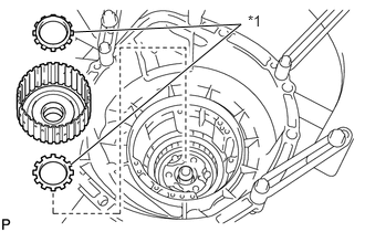
| *1 | Thrust Needle Roller Bearing |
Remove the planetary sun gear sub-assembly.
Remove the 2 thrust needle roller bearings from the front planetary sun gear sub-assembly.
35709K
36.REMOVE REAR PLANETARY GEAR SUB-ASSEMBLY
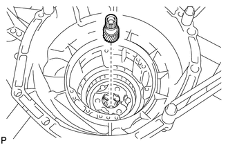
Remove the rear planetary gear sub-assembly.
37.MEASURE BRAKE DISC END PLAY
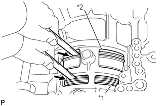
| *1 | 1st and Reverse Brake |
| *2 | 2nd and 4th Brake |
Using a feeler gauge, measure the 1st and reverse brake and 2nd and 4th brake end play.
- Standard end play:
- 1st and reverse brake:
for 1NR-VE: 0.69 to 1.18 mm (0.0270 to 0.0463 in.)
for 2NR-VE: 0.65 to 1.14 mm (0.0254 to 0.0447 in.)
- 2nd and 4th brake:
for 1NR-VE: 1.08 to 1.53 mm (0.0424 to 0.0604 in.)
for 2NR-VE: 1.07 to 1.52 mm (0.0420 to 0.0600 in.)
- HINT:
-
If the measured end play fails to conform to the specified value above, select a snap ring.
35681
38.REMOVE NO. 1 BRAKE DISC
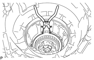
Using snap ring pliers, remove the hole snap ring.
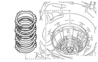
for 1NR-VE
Remove the 2 No. 1 brake flanges, 2 brake plates and 3 No. 1 brake discs.
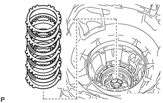
for 2NR-VE
Remove the 2 No. 1 brake flanges, 3 brake plates and 4 No. 1 brake discs.
35624E
39.REMOVE 2ND AND 4TH BRAKE PISTON
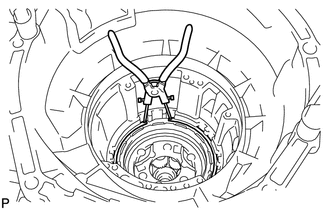
Using snap ring pliers, remove the hole snap ring.
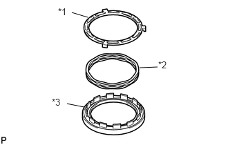
| *1 | 2nd and 4th Brake Piston Return Spring Seat |
| *2 | 2nd and 4th Brake Piston Return Spring |
| *3 | 2nd and 4th Brake Piston |
Remove the 2nd and 4th brake piston return spring seat, 2nd and 4th brake piston return spring, 2nd and 4th brake piston and 2nd and 4th brake cylinder.
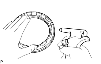
Apply compressed air to the oil hole to remove the 2nd and 4th brake piston from the 2nd and 4th brake cylinder.
- HINT:
-
When the piston can not be removed as it is slanted, either blow the air again while holding down the protruding side by hand or remove the piston using needle nose pliers with tape on the tip.
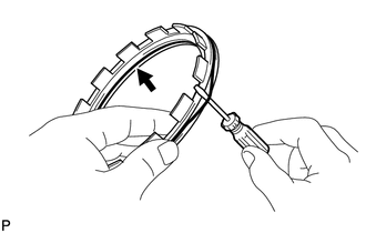
Using a screwdriver, remove the 2 O-rings from the 2nd and 4th brake piston.
35720
40.REMOVE FRONT PLANETARY GEAR ASSEMBLY
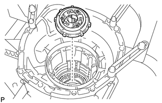
Remove the front planetary gear assembly and the 1 way clutch assembly from the transmission case.
35790A
41.REMOVE 1 WAY CLUTCH ASSEMBLY
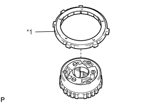
| *1 | 1 way clutch assembly |
Remove the 1 way clutch assembly from the planetary gear assembly.
35883A
42.REMOVE BRAKE DISC
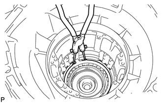
Using snap ring pliers, remove the hole snap ring.
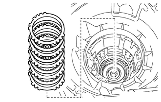
for 1NR-VE
Remove the brake flange, 4 brake discs and 4 brake plates.
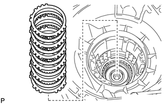
for 2NR-VE
Remove the brake flange, 5 brake discs and 5 brake plates.
35740A
43.REMOVE FRONT PLANETARY RING GEAR ASSEMBLY
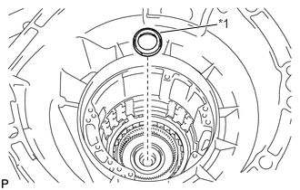
| *1 | Thrust Needle Roller Bearing |
Remove the thrust needle roller bearing from the front planetary ring gear assembly.
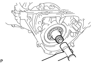
Tap on the circumference of the front planetary ring gear assembly with a plastic hammer to remove the front planetary ring gear assembly.
- NOTICE:
-
In case that the front planetary ring gear assembly is dropped, hold it with hand while removal.
35775F
44.REMOVE RADIAL BALL BEARING
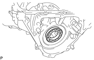
Remove the radial ball bearing from the transmission case.
- HINT:
-
If any difficulty is encountered in removing the radial ball bearing, remove it by applying a light impact from the inside of the transmission case, using a brass bar and a plastic hammer.
35623S
45.REMOVE 1ST AND REVERSE BRAKE PISTON
| *a | Deformation |
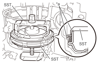
Place SST on the 1st and reverse brake piston return spring seat and compress the 1st and reverse brake piston return spring.
- SST
- 09351-87201
09351-97201
- HINT:
-
To prevent deformation, be sure to stop tightening the SST when the spring has been lowered 1 to 2 mm (0.04 to 0.08 in.) from the snap ring installation groove.
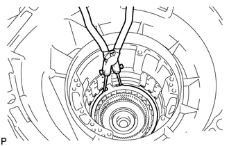
Using snap ring pliers, remove the hole snap ring.
Remove the 1st and reverse brake piston return spring seat and 1st and reverse brake piston return spring.
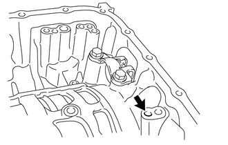
Apply compressed air (392 to 784 kPa, 4 to 8 kgf/cm2, 57 to 114 psi) into the transmission case to remove the 1st and reverse brake piston.
- NOTICE:
-
Be careful to avoid splashing oil when applying compressed air.
85420
46.REMOVE TRANSMISSION SOLENOID ASSEMBLY
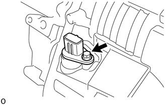
Remove the bolt and transmission solenoid assembly.
Remove the O-ring.