BRAKE CONTROL / DYNAMIC CONTROL SYSTEMS VEHICLE STABILITY CONTROL SYSTEM C1249/39 Stop Lamp SW Open Wire C1328/98 Stop Lamp SW Check Non-completion (Check Mode)
DESCRIPTION
The skid control ECU (brake actuator assembly) has an open detection circuit, which outputs this DTC when detecting open circuits in the stop light input line of the stop light LH and RH circuits or an open in the ground line with the stop light switch off (brake pedal not depressed).
DTC C1328/98 is cleared when the stop light switch sends a vehicle speed signal or when Test Mode ends. DTC C1328/98 is output only in Test Mode.
| DTC No. | Detection Item | DTC Detection Condition | Trouble Area | Note |
|---|---|---|---|---|
| C1249/39 | Stop Lamp SW Open Wire | With ignition switch ON, there is a continuous open-circuit in the stop light system. | ·
Deformation, damage, or poor connections of connector terminals ·
Stop light switch assembly malfunction, poor connection, and corrosion ·
Open of wire harness ·
Resistance open-circuit due to corrosion on stop light system, or burned light bulb ·
Skid control ECU (brake actuator assembly) ·
Main body ECU (Fuse block assembly) |
- |
| C1328/98 | Stop Lamp SW Check Non-completion (Check Mode) | Stored during Test Mode. | ·
Deformation, damage, or poor connections of connector terminals ·
Stop light switch assembly malfunction, poor connection, and corrosion ·
Open of wire harness ·
Resistance open-circuit or burned light bulb due to corrosion on stop light system ·
Skid control ECU (brake actuator assembly) ·
Main body ECU (Fuse block assembly) |
- |
WIRING DIAGRAM
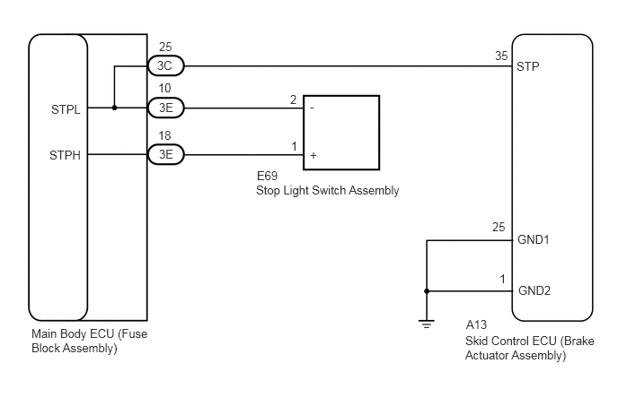
CAUTION / NOTICE / HINT
- NOTICE:
- ·
Inspect the fuses for circuits related to this system before performing the following inspection procedure.
·If the skid control ECU (brake actuator assembly) is replaced with a new one, the skid control ECU (brake actuator assembly) makes the shift to test mode automatically when the ignition switch is turned to ON for the first time. Be sure to complete the test mode checks.
Click hereBrake>BRAKE CONTROL / DYNAMIC CONTROL SYSTEMS>VEHICLE STABILITY CONTROL SYSTEM>TEST MODE PROCEDURE
PROCEDURE
Check the brake pedal height and stop light switch assembly installation.
for LHD: Click hereBrake>BRAKE SYSTEM (OTHER)>2NR-VE BRAKE PEDAL(for LHD)>ADJUSTMENT
for RHD: Click hereBrake>BRAKE SYSTEM (OTHER)>BRAKE PEDAL(for RHD)>ADJUSTMENT
- OK:
The brake pedal height and stop light switch assembly installation are normal.
- HINT:
-
If the on/off status of the stop light switch assembly and the pressure increase information from the master cylinder pressure sensor do not match due to an improperly installed brake pedal or stop light switch assembly, this DTC may be stored. Therefore, be sure to check the installation condition of the pedal and stop light switch assembly before inspecting the input signals and other related parts.
- Result:
Proceed to OK NG
OK
NG
for LHD: Click hereBrake>BRAKE SYSTEM (OTHER)>2NR-VE BRAKE PEDAL(for LHD)>ADJUSTMENT
for RHD: Click hereBrake>BRAKE SYSTEM (OTHER)>BRAKE PEDAL(for RHD)>ADJUSTMENT
Check that the stop lights come on when the brake pedal is depressed, and go off when the brake pedal is released.
- OK:
Condition Illumination Condition Brake pedal depressed. On Brake pedal released. Off
- Result:
Proceed to OK NG
OK
NG
Turn the ignition switch off.
Disconnect the A13 skid control ECU (brake actuator assembly) connector.
Disconnect the 3C main body ECU (fuse block assembly) connector.
Measure the resistance according to the value(s) in the table below.
- Standard Resistance (Check for Open):
Tester Connection Condition Specified Condition A13-35 (STP) - 3C-25 Always Below 1 Ω
- Standard Resistance (Check for Open):
Tester Connection Condition Specified Condition A13-35 (STP) - Body ground Always 10 kΩ or higher 3C-25 - Body ground Always 10 kΩ or higher
- Result:
Proceed to OK NG
OK
NG
Turn the ignition switch off.
Disconnect the A13 skid control ECU (brake actuator assembly) connector.
Measure the resistance according to the value(s) in the table below.
- Standard Resistance (Check for Open):
Tester Connection Condition Specified Condition A13-25 (GND1) - Body ground Always Below 1 Ω A13-1 (GND2) - Body ground Always Below 1 Ω
- Result:
Proceed to OK NG
OK
NG
Turn the ignition switch off.
Clear the DTCs.
Click hereBrake>BRAKE CONTROL / DYNAMIC CONTROL SYSTEMS>VEHICLE STABILITY CONTROL SYSTEM>DTC CHECK / CLEAR
Turn the ignition switch off.
Start the engine.
Drive the vehicle and depress the brake pedal several times to test the stop light circuit.
Check if the same DTC is output.
Click hereBrake>BRAKE CONTROL / DYNAMIC CONTROL SYSTEMS>VEHICLE STABILITY CONTROL SYSTEM>DTC CHECK / CLEAR
- Result:
Result Proceed to DTC C1249 is not output. A DTC C1249 is output. B
- HINT:
-
If troubleshooting has been carried out according to Problem Symptoms Table, refer back to the table and proceed to the next step before replacing parts.
A
Click hereGeneral>INTRODUCTION>HOW TO TROUBLESHOOT ECU CONTROLLED SYSTEMS>HOW TO PROCEED WITH TROUBLESHOOTING
B