BRAKE CONTROL / DYNAMIC CONTROL SYSTEMS VEHICLE STABILITY CONTROL SYSTEM TEST MODE PROCEDURE
WARNING LIGHT AND INDICATOR LIGHT INITIAL CHECK
Release the parking brake.
- NOTICE:
-
Before releasing the parking brake, move the shift lever to P for safety (for automatic transmission), move the shift lever to N for safety use wheel chocks to secure the vehicle (for manual transmission).
- HINT:
-
When the parking brake is applied or the brake fluid level is low, the brake warning light comes on.
When the ignition switch is turned to ON, check that the ABS warning light, Brake warning light, VSC OFF indicator light, TRC OFF indicator and slip indicator light come on for approximately 3 seconds.
- HINT:
- ·
If the skid control ECU (brake actuator assembly) stores a DTC, the ABS warning and slip indicator lights will come on.
·If any of the indicators remains on or does not come on, proceed to troubleshooting for the light circuits listed below.
| Trouble Area | See procedure |
|---|---|
| ABS warning light circuit (Remains on) | ( ) |
| ABS warning light circuit (Does not come on) | ()
|
| Brake warning light circuit (Remains on) | ()
|
| Brake warning light circuit (Does not come on) | ()
|
| TRC OFF indicator light circuit (Remains on) | ()
|
| TRC OFF indicator light circuit (Does not come on) | ()
|
| VSC OFF indicator light circuit (Remains on) | ()
|
| VSC OFF indicator light circuit (Does not come on) | ()
|
| Slip indicator light circuit (Remains on) | ()
|
| Slip indicator light circuit (Does not come on) | ()
|
SENSOR CHECK USING TEST MODE (Using the GTS)
- NOTICE:
- ·
Perform a Test Mode check after replacing the skid control ECU (brake actuator assembly), yaw rate and G sensor (brake actuator assembly) or steering sensor (switch base).
·The system automatically enters Test Mode when the ignition switch is turned to ON for the first time after the skid control ECU (brake actuator assembly) is replaced.
- HINT:
- ·
When entering the Test Mode, all the Test Mode codes are stored temporarily, and then the codes judged to be normal are cleared.
·VSC does not operate in Test Mode, regardless of whether the sensor check is normal or abnormal.
·If any of the sensors malfunction, the ABS warning light, brake warning light, and slip indicator light come on, and ABS does not function.
·All the Test Mode codes are cleared when the mode returns to the normal mode.
Procedure to Enter Test Mode
Turn the ignition switch off.
Apply the parking brake.
Check that the steering wheel is centered.
Check that the shift lever is in neutral (for Manual Transmission).
Check that the shift lever is in P (for Automatic Transmission).
Connect the GTS to the DLC3.
Turn the ignition switch to ON.
Turn the GTS on.
Switch the skid control ECU (brake actuator assembly) to test mode using the GTS. Enter the following menus: Chassis / ABS/VSC/TRC / Utility / Signal Check.
Test Mode Display Check
Check that the ABS warning and VSC OFF indicator light comes on for several seconds and then blinks in the test mode pattern (0.12 seconds on and 0.12 seconds off).
- HINT:
-
If the ABS warning and VSC OFF indicator light does not blink, inspect the ABS warning and VSC OFF indicator light circuit.
Zero point calibration of the yaw rate sensor, G sensor and master cylinder pressure sensor
- NOTICE:
- ·
Perform this work on a level surface.
·Do not subject the vehicle to shocks during the calibration process.
With the ignition switch ON (engine stopped), apply the parking brake.
Press the VSC OFF switch.
- HINT:
-
Perform the above step within 2 seconds after entering the Test Mode.
Check that the slip indicator light comes on.
Check that the slip indicator light goes off in 1 second and the buzzer sounds.
- HINT:
-
Perform the above steps with the brake pedal released.
Right/Left G sensor Check
- NOTICE:
- ·
Perform the right/left G sensor check after completing zero point calibration for each sensor.
·This check can be performed at the same time as the output test for the other sensors.
Get into and out of the driver seat.
- HINT:
-
A slight change in weight distribution affected by getting into and out of the driver seat is sufficient to check the functionality of the G sensor.
Yaw Rate Sensor Check
- NOTICE:
- ·
Perform the yaw rate sensor check after completing zero point calibration for each sensor.
·The yaw rate sensor check, steering sensor (switch base) check, and wheel speed sensor check can be performed at the same time.
Start the engine.
Drive the vehicle and turn the steering wheel to the right or left.
- HINT:
-
Turn the vehicle so that the yaw rate is greater than 3°/s.
Steering Sensor (Switch Base) Check
- NOTICE:
-
The yaw rate sensor check, steering sensor (switch base) check, and wheel speed sensor check can be performed at the same time.
Start the engine.
Turn the steering wheel 90 degrees or more.
- HINT:
-
This step can be performed with the vehicle running or stopped.
Check that the VSC OFF indicator light goes off.
Stop Light Switch Check
- HINT:
-
This check can be performed at the same time as the Front/Rear G sensor Check and Wheel Speed Sensor Check.
Start the engine.
Drive the vehicle and apply brake normally to stop the vehicle.
Front/Rear G Sensor Check
Start the engine.
Drive the vehicle and apply brake normally to stop the vehicle.
- HINT:
- ·
Perform the above step after more than 5 seconds have elapsed since the mode switched to the Test Mode.
·A light braking force of about 0.1 G is sufficient to check the functionality of the Front/Rear G sensor.
Wheel Speed Sensor Check
- NOTICE:
-
The yaw rate sensor check, steering sensor (switch base) check, and wheel speed sensor check can be performed at the same time.
Start the engine.
Drive the vehicle straight ahead at a vehicle speed range of approximately 30 km/h to 40 km/h for 2 seconds or more.
- NOTICE:
-
The speed sensor check may not be completed if the speed sensor check is started while turning the steering wheel or spinning the wheels.
Stop the vehicle.
Check that the ABS light warning lamp goes out.
- NOTICE:
-
If the stop light switch check has not been completed, the ABS warning light will blink while driving and the ABS will not operate.
End of Test Mode
If all the items are completed with no abnormalities detected, all the Test Mode codes are cleared and the ABS warning light and the VSC OFF indicator light will go off.
- NOTICE:
- ·
When the cancelling conditions of the Test Mode codes are met and all the Test Mode codes are cleared, the Test Mode will end.
·If the sensor check has not been performed yet, or if any of the sensors malfunction, the ABS warning light and VSC OFF indicator light will blink, and ABS does not function.
·If any DTCs are detected during the Test Mode, the ABS warning light, brake warning light, and slip indicator light come on.
·If DTCs are detected or Test Mode codes cannot be cleared, repair the failed part corresponding to the code.
Read Test Mode code
While staying in Test Mode, check for DTC using the GTS.
Exit Test Mode
Enter the following menus: Chassis / ABS/VSC/TRC / Utility / Signal Check.
Turn the ignition switch off and disconnect the GTS.
Check the DTCs in test mode.
| DTC No. | Detection Item | Cancel Condition |
|---|---|---|
| C1210 | Zero Point Calibration of Yaw Rate Sensor Undone (Check Mode) | Zero point calibration of the yaw rate sensor is complete |
| C1275 | Abnormal Cycle of FR Wheel (Check Mode) | Vehicle is driven at approximately 30km/h (19 mph) to 40km/h (25 mph) and all wheel speed sensor outputs are normal |
| C1276 | Abnormal Cycle of FL Wheel (Check Mode) | Vehicle is driven at approximately 30km/h (19 mph) to 40km/h (25 mph) and all wheel speed sensor outputs are normal |
| C1277 | Abnormal Cycle of RR Wheel (Check Mode) | Vehicle is driven at approximately 30km/h (19 mph) to 40km/h (25 mph) and all wheel speed sensor outputs are normal |
| C1278 | Abnormal Cycle of RL Wheel (Check Mode) | Vehicle is driven at approximately 30km/h (19 mph) to 40km/h (25 mph) and all wheel speed sensor outputs are normal |
| C1279 | G Sensor (Check Mode) | No output-stuck of G sensor or no abnormal output when vehicle is stopped |
| C1281 | Master Hydraulic Pressure System (Check Mode) | Zero point calibration of the master cylinder pressure sensor is complete |
| C1322 | STS System Grounded | Change in output |
| C1323 | Wheel Speed Sensor Total Check Non-completion (Check Mode) | Vehicle is driven at approximately 30km/h (19 mph) to 40km/h (25 mph) and all wheel speed sensor outputs are normal |
| C1327 | Zero Point Calibration of Right / Left G Sensor Undone (Check Mode) | Zero point calibration of the G sensor is complete |
| C1328 | Stop Lamp SW Check Non-completion (Check Mode) | Stop light switch assemgly ON/OFF |
| C1336 | Zero Point Calibration of G Sensor Undone (Check Mode) | Zero point calibration of the G sensor is complete |
| C1393 | Yaw Rate Sensor (Check Mode) | Output change of more than 3°/s |
| C1394 | Steering Angle Sensor (Check Mode) | Output change of more than 90° |
SENSOR CHECK USING TEST MODE (Using SST Check Wire)
- NOTICE:
- ·
Perform a Test Mode check after replacing the skid control ECU (brake actuator assembly), yaw rate and G sensor (brake actuator assembly) or steering sensor (switch base).
·The system automatically enters Test Mode when the ignition switch is turned to ON for the first time after the skid control ECU (brake actuator assembly) is replaced.
- HINT:
- ·
When entering the Test Mode, all the Test Mode codes are stored temporarily, and then the codes judged to be normal are cleared.
·VSC does not operate in Test Mode, regardless of whether the sensor check is normal or abnormal.
·If any of the sensors malfunction, the ABS warning light, brake warning light, and slip indicator light come on, and ABS does not function.
·All the Test Mode codes are cleared when the mode returns to the normal mode.
Procedure to Enter Test Mode
Turn the ignition switch off.
Apply the parking brake.
Check that the steering wheel is centered.
Check that the shift lever is in neutral (for Manual Transmission).
Check that the shift lever is in P (for Automatic Transmission).
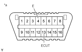
| *a | Front view of DLC3 |
Using SST, connect terminals 13 (ECUT) and 4 (E) of the DLC3.
- SST
- 09843-18040
Turn the ignition switch to ON.
Disconnect SST from terminals 4 (E) and 13 (ECUT) of the DLC3.
Test Mode Display Check
Check that the ABS warning and VSC OFF indicator light comes on for several seconds and then blinks in the test mode pattern (0.12 seconds on and 0.12 seconds off).
- HINT:
-
If the ABS warning and VSC OFF indicator light does not blink, inspect the ABS warning and VSC OFF indicator light circuit.
Zero point calibration of the yaw rate sensor, G sensor and master cylinder pressure sensor
- NOTICE:
- ·
Perform this work on a level surface.
·Do not subject the vehicle to shocks during the calibration process.
With the ignition switch ON (engine stopped), apply the parking brake.
Press the VSC OFF switch.
- HINT:
-
Perform the above step within 2 seconds after entering the Test Mode.
Check that the slip indicator light comes on.
Check that the slip indicator light goes off in 1 second and the buzzer sounds.
- HINT:
-
Perform the above steps with the brake pedal released.
Right/Left G Sensor Check
- NOTICE:
- ·
Perform the right/left G sensor check after completing zero point calibration for each sensor.
·This check can be performed at the same time as the output test for the other sensors.
Get into and out of the driver seat.
- HINT:
-
A slight change in weight distribution affected by getting into and out of the driver seat is sufficient to check the functionality of the G sensor.
Yaw Rate Sensor Check
- NOTICE:
- ·
Perform the yaw rate sensor check after completing zero point calibration for each sensor.
·The yaw rate sensor check, steering sensor (switch base) check, and wheel speed sensor check can be performed at the same time.
Start the engine.
Drive the vehicle and turn the steering wheel to the right or left.
- HINT:
-
Turn the vehicle so that the yaw rate is greater than 3°/s.
Steering Sensor (Switch Base) Check
- NOTICE:
-
The yaw rate sensor check, steering sensor (switch base) check, and wheel speed sensor check can be performed at the same time.
Start the engine.
Turn the steering wheel 90 degrees or more.
- HINT:
-
This step can be performed with the vehicle running or stopped.
Check that the VSC OFF indicator light goes off.
Stop Light Switch Check
- HINT:
-
This check can be performed at the same time as the front/rear G sensor check and wheel speed sensor check.
Start the engine.
Drive the vehicle and apply brake normally to stop the vehicle.
Front/Rear G Sensor Check
Start the engine.
Drive the vehicle and apply brake normally to stop the vehicle.
- HINT:
- ·
Perform the above step after more than 5 seconds have elapsed since the mode switched to the Test Mode.
·A light braking force of about 0.1 G is sufficient to check the functionality of the Front/Rear G sensor.
Wheel Speed Sensor Check
- NOTICE:
-
The yaw rate sensor check, steering sensor (switch base) check, and wheel speed sensor check can be performed at the same time.
Start the engine.
Drive the vehicle straight ahead at a vehicle speed range of approximately 30 to 40 km/h (19 to 25 mph) for 2 seconds or more.
- NOTICE:
-
The speed sensor check may not be completed if the speed sensor check is started while turning the steering wheel or spinning the wheels.
Stop the vehicle.
Check that the ABS warning light goes out.
- NOTICE:
-
If the stop light switch check has not been completed, the ABS warning light will blink while driving and the ABS will not operate.
End of Test Mode
If all the items are completed with no abnormalities detected, all the Test Mode codes are cleared and the ABS warning light and the VSC OFF indicator light will go off.
- NOTICE:
- ·
When the cancelling conditions of the Test Mode codes are met and all the Test Mode codes are cleared, the Test Mode will end.
·If the sensor check has not been performed yet, or if any of the sensors malfunction, the ABS warning light and VSC OFF indicator light will blink, and ABS does not function.
·If any DTCs are detected during the Test Mode, the ABS warning light, brake warning light, and slip indicator light come on.
·If DTCs are detected or Test Mode codes cannot be cleared, repair the failed part corresponding to the code.
Read Test Mode code
Turn the ignition switch off.
| *a | Front view of DLC3 |
Using SST, connect terminals 13 (ECUT) and 4 (E) of the DLC3.
- SST
- 09843-18040
- NOTICE:
- ·
Make sure to use the specified SST to connect terminals.
·To avoid malfunction, be careful not to connect wrong terminals of DLC3.
·The above step must be performed with the vehicle stopped.
Turn the ignition switch to ON.
- HINT:
-
If the ignition switch is not turned to ON after SST is removed from the DLC3, the previous test mode continues.
Count the number of blinks of the ABS warning light and VSC OFF indicator light.
- NOTICE:
- ·
If only DTCs other than test mode sensor check DTCs are output, repair the malfunctions and clear the DTCs.
·If only Test Mode codes are output, repair the corresponding failed part and perform the test again.
·If test mode (signal check) DTCs and other DTCs are output or if only test mode (signal check) DTCs are output, repair the malfunctions, clear the DTCs, and perform the test mode (signal check) inspection again.
- HINT:
- ·
Test Mode codes and DTCs are displayed.
·When the system is normal, the ABS warning light blinks at 0.25 seconds intervals (0.25 seconds on and 0.25 seconds off).
·When only 1 DTC is output, the light outputs the same code after an interval of 4 seconds.
Example: when DTC 21 is output, the light blinks twice, turns off for 1.5 seconds, blinks once, turns off for 4 seconds, and then repeats this output pattern.
·When 2 or more DTCs are output, the light outputs the codes with an interval of 2.5 seconds between each different code, and the output of all codes repeats after an interval of 4 seconds.
·If more than 1 malfunction is detected at the same time, the lowest numbered code is output first.
Exit Test Mode
When each sensor check and the stop light switch assembly check are performed, and all the test items are completed with no abnormalities detected, the Test Mode will end.
Check the DTCs in test mode.
| DTC No. | Detection Item | Cancel Condition |
|---|---|---|
| 85 | Abnormal Cycle of FR Wheel (Check Mode) | Vehicle is driven at approximately 30km/h (19 mph) to 40km/h (25 mph) and all wheel speed sensor outputs are normal |
| 86 | Abnormal Cycle of FL Wheel (Check Mode) | Vehicle is driven at approximately 30km/h (19 mph) to 40km/h (25 mph) and all wheel speed sensor outputs are normal |
| 87 | Abnormal Cycle of RR Wheel (Check Mode) | Vehicle is driven at approximately 30km/h (19 mph) to 40km/h (25 mph) and all wheel speed sensor outputs are normal |
| 88 | Abnormal Cycle of RL Wheel (Check Mode) | Vehicle is driven at approximately 30km/h (19 mph) to 40km/h (25 mph) and all wheel speed sensor outputs are normal |
| 91 | G Sensor (Check Mode) | No output-stuck of G sensor or no abnormal output when vehicle is stopped |
| 92 | Zero Point Calibration of G Sensor Undone (Check Mode) | Zero point calibration of the G sensor is complete |
| 93 | Yaw Rate Sensor (Check Mode) | Output change of more than 3°/s |
| 93 | Zero Point Calibration of Yaw Rate Sensor Undone (Check Mode) | Zero point calibration of the yaw rate sensor is complete |
| 94 | Steering Angle Sensor (Check Mode) | Output change of more than 90° |
| 95 | Master Hydraulic Pressure System (Check Mode) | Zero point calibration of the master cylinder pressure sensor is complete |
| 96 | Wheel Speed Sensor Total Check Non-completion (Check Mode) | Vehicle is driven at approximately 30km/h (19 mph) to 40km/h (25 mph) and all wheel speed sensor outputs are normal |
| 97 | STS System Grounded | Change in output |
| 98 | Stop Lamp SW Check Non-completion (Check Mode) | Stop light switch assemgly ON/OFF |
| 99 | Zero Point Calibration of Right / Left G Sensor Undone (Check Mode) | Zero point calibration of the G sensor is complete |