BRAKE CONTROL / DYNAMIC CONTROL SYSTEMS VEHICLE STABILITY CONTROL SYSTEM C1275/85 Abnormal Cycle of FR Wheel (Check Mode) C1276/86 Abnormal Cycle of FL Wheel (Check Mode) C1277/87 Abnormal Cycle of RR Wheel (Check Mode) C1278/88 Abnormal Cycle of RL Wheel (Check Mode) C1323/96 Wheel Speed Sensor Total Check Non-completion (Check Mode)
DESCRIPTION
The skid control ECU (brake actuator assembly) measures the speed of each wheel by receiving signals from the speed sensors.
These signals are used for recognizing that all 4 wheels are operating properly.
Therefore, all wheel signals must indicate the same speed.
DTCs C1275/85 to C1278/88 are cleared when the speed sensor sends a vehicle speed signal or Test Mode ends. DTCs C1275/85 to C1278/88 are output only in Test Mode.
- HINT:
-
When the connectors between the speed sensor and skid control ECU (brake actuator assembly) are connected, the following waveform is output.
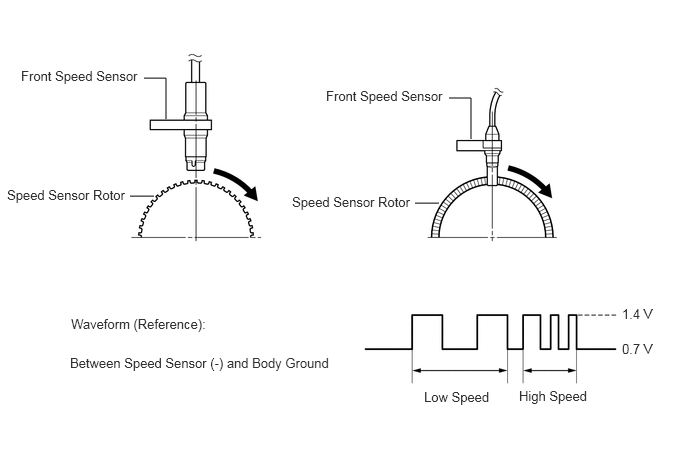
| DTC No. | Detection Item | DTC Detection Condition | Trouble Area | Note |
|---|---|---|---|---|
| C1275/85 | Abnormal Cycle of FR Wheel (Check Mode) | Stored during Test Mode. | Speed sensor rotor (Front axle hub bearing or rear axle hub and bearing assembly) | - |
| C1276/86 | Abnormal Cycle of FL Wheel (Check Mode) | Stored during Test Mode. | Speed sensor rotor (Front axle hub bearing or rear axle hub and bearing assembly) | - |
| C1277/87 | Abnormal Cycle of RR Wheel (Check Mode) | Stored during Test Mode. | Speed sensor rotor (Front axle hub bearing or rear axle hub and bearing assembly) | - |
| C1278/88 | Abnormal Cycle of RL Wheel (Check Mode) | Stored during Test Mode. | Speed sensor rotor (Front axle hub bearing or rear axle hub and bearing assembly) | - |
| C1323/96 | Wheel Speed Sensor Total Check Non-completion (Check Mode) | Stored during Test Mode. | Speed sensor rotor (Front axle hub bearing or rear axle hub and bearing assembly) | - |
- HINT:
- ·
DTC C1275/85 is for the front speed sensor RH.
·DTC C1276/86 is for the front speed sensor LH.
·DTC C1277/87 is for the rear speed sensor RH.
·DTC C1278/88 is for the rear speed sensor LH.
WIRING DIAGRAM
For front speed sensors, refer to DTCs C0200/21, C0205/22.
Click hereBrake>BRAKE CONTROL / DYNAMIC CONTROL SYSTEMS>VEHICLE STABILITY CONTROL SYSTEM>C0200/21
For rear speed sensors, refer to DTCs C0210/23, C0215/24 .
Click hereBrake>BRAKE CONTROL / DYNAMIC CONTROL SYSTEMS>VEHICLE STABILITY CONTROL SYSTEM>C0210/23
CAUTION / NOTICE / HINT
- NOTICE:
- ·
Inspect the fuses for circuits related to this system before performing the following inspection procedure.
·If the skid control ECU (brake actuator assembly) is replaced with a new one, the skid control ECU (brake actuator assembly) makes the shift to test mode automatically when the ignition switch is turned to ON for the first time. Be sure to complete the test mode checks (Click hereBrake>BRAKE CONTROL / DYNAMIC CONTROL SYSTEMS>VEHICLE STABILITY CONTROL SYSTEM>TEST MODE PROCEDURE).
PROCEDURE
Turn the ignition switch off.
Make sure that there is no looseness in the locking part and connecting part of the connectors.
Disconnect the A13 skid control ECU (brake actuator assembly) connector.
Disconnect the A31*1 or A32*2 front speed sensor and/or J2*1 or J7*2 rear speed sensor connector.
*1: for RH
*2: for LH
Measure the resistance according to the value(s) in the table below.
- Standard Resistance (Check for Open):
- for Front RH:
Tester Connection Condition Specified Condition A13-31 (FR1) - A31-1 (+) Always Below 1 Ω A13-30 (FR0) - A31-2 (-) Always Below 1 Ω
- for Front LH:
Tester Connection Condition Specified Condition A13-18 (FL1) - A32-1 (+) Always Below 1 Ω A13-17 (FL0) - A32-2 (-) Always Below 1 Ω
- for Rear RH:
Tester Connection Condition Specified Condition A13-16 (RR1) - J2-1 (+) Always Below 1 Ω A13-15 (RR0) - J2-2 (-) Always Below 1 Ω
- for Rear LH:
Tester Connection Condition Specified Condition A13-29 (RL1) - J7-1 (+) Always Below 1 Ω A13-28 (RL0) - J7-2 (-) Always Below 1 Ω
- Standard Resistance (Check for Short):
- for Front RH:
Tester Connection Condition Specified Condition A13-31 (FR1) or A31-1 (+) - Body ground Always 10 kΩ or higher A13-30 (FR0) or A31-2 (-) - Body ground Always 10 kΩ or higher
- for Front LH:
Tester Connection Condition Specified Condition A13-18 (FL1) or A32-1 (+) - Body ground Always 10 kΩ or higher A13-17 (FL0) or A32-2 (-) - Body ground Always 10 kΩ or higher
- for Rear RH:
Tester Connection Condition Specified Condition A13-16 (RR1) or J2-1 (+) - Body ground Always 10 kΩ or higher A13-15 (RR0) or J2-2 (-) - Body ground Always 10 kΩ or higher
- for Rear LH:
Tester Connection Condition Specified Condition A13-29 (RL1) or J7-1 (+) - Body ground Always 10 kΩ or higher A13-28 (RL0) or J7-2 (-) - Body ground Always 10 kΩ or higher
- NOTICE:
-
Check the speed sensor signal after repair or replacement (Click hereBrake>BRAKE CONTROL / DYNAMIC CONTROL SYSTEMS>VEHICLE STABILITY CONTROL SYSTEM>TEST MODE PROCEDURE).
- Result:
Proceed to OK NG
OK
NG
Perform the speed sensor check in the test mode procedure.
Click hereBrake>BRAKE CONTROL / DYNAMIC CONTROL SYSTEMS>VEHICLE STABILITY CONTROL SYSTEM>TEST MODE PROCEDURE
- OK:
All Test Mode DTCs are cleared.
- Result:
Result Proceed to DTCs are not cleared. Front speed sensor A Rear speed sensor B DTCs are cleared. C
A
B
C
Turn the ignition switch off.
Replace the front speed sensor.
Click hereBrake>BRAKE CONTROL / DYNAMIC CONTROL SYSTEMS>FRONT SPEED SENSOR>REMOVAL
- Result:
Proceed to NEXT
NEXT
Clear the DTCs.
Click hereBrake>BRAKE CONTROL / DYNAMIC CONTROL SYSTEMS>VEHICLE STABILITY CONTROL SYSTEM>DTC CHECK / CLEAR
Turn the ignition switch off.
Start the engine.
Drive the vehicle at a speed of 20 km/h (12 mph) or more for at least 30 seconds.
Check if the same DTC is output.
Click hereBrake>BRAKE CONTROL / DYNAMIC CONTROL SYSTEMS>VEHICLE STABILITY CONTROL SYSTEM>DTC CHECK / CLEAR
- OK:
DTC is not output.
- Result:
Proceed to OK NG
OK
NG
Turn the ignition switch off.
Replace the rear speed sensor.
- Result:
Proceed to NEXT
NEXT
Clear the DTCs.
Click hereBrake>BRAKE CONTROL / DYNAMIC CONTROL SYSTEMS>VEHICLE STABILITY CONTROL SYSTEM>DTC CHECK / CLEAR
Turn the ignition switch off.
Start the engine.
Drive the vehicle at a speed of 20 km/h (12 mph) or more for at least 30 seconds.
Check if the same DTC is output.
Click hereBrake>BRAKE CONTROL / DYNAMIC CONTROL SYSTEMS>VEHICLE STABILITY CONTROL SYSTEM>DTC CHECK / CLEAR
- OK:
DTC is not output.
- Result:
Proceed to OK NG
OK
NG