HEATING / AIR CONDITIONING COMPRESSOR REMOVAL
CAUTION / NOTICE / HINT
The necessary procedures (adjustment, calibration, initialization, or registration) that must be performed after parts are removed, installed, or replaced during the compressor with motor assembly removal/installation are shown below.
| Replaced Part or Performed Procedure | Necessary Procedure | Effect/Inoperative when not Performed | Link |
|---|---|---|---|
| Disconnect cable from negative auxiliary battery terminal | Memorize steering angle neutral point | Lane departure alert system (w/ Steering Control) | ( ) |
| Simple intelligent parking assist system*1 | |||
| Toyota parking assist-sensor system*1 | |||
| Pre-collision system | |||
| Initialize back door lock | Power door lock control system | ()
|
*1: When performing learning using the GTS.
- CAUTION:
- ·
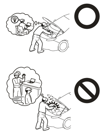
This vehicle has contains high voltage circuits standardized with orange colored wiring and connectors, so follow the instructions in this manual to perform the procedures correctly.
Click hereEngine / Hybrid System>HYBRID / BATTERY CONTROL>HYBRID CONTROL SYSTEM>PRECAUTION
·If the correct procedures are not followed according to the instructions in this manual, there is a danger of electric shock from the high voltage circuits.
·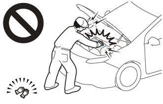
Be sure to wear insulating gloves when working on high voltage wiring or components.
·If work is performed without wearing insulating gloves, there is a danger of electric shock.
PROCEDURE

 1.RECOVER REFRIGERANT FROM REFRIGERATION SYSTEM
G3834
2.REMOVE SERVICE PLUG GRIP
82121
3.DISCONNECT ENGINE WIRE
4.REMOVE CONNECTOR COVER ASSEMBLY
5.CHECK TERMINAL VOLTAGE
6.INSTALL CONNECTOR COVER ASSEMBLY
82121
7.CONNECT ENGINE WIRE
51441
8.REMOVE NO. 1 ENGINE UNDER COVER
88703
9.DISCONNECT DISCHARGE HOSE SUB-ASSEMBLY
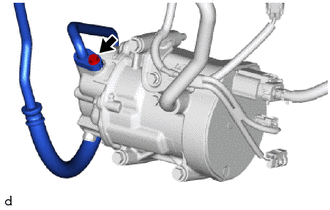
Remove the bolt to disconnect the discharge hose sub-assembly from the compressor with motor assembly.
Remove the O-ring from the refrigerant discharge hose sub-assembly.
- NOTICE:
-
Wrap protective tape around the connecting portions of the disconnected refrigerant discharge hose sub-assembly and compressor with motor assembly to prevent contamination by foreign matter or water droplets.
88704
10.DISCONNECT SUCTION HOSE SUB-ASSEMBLY
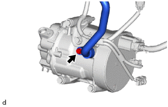
Remove the bolt to disconnect the suction hose sub-assembly from the compressor with motor assembly.
Remove the O-ring from the suction hose sub-assembly.
- NOTICE:
-
Wrap protective tape around the connecting portions of the disconnected suction hose sub-assembly and the compressor with motor assembly to prevent contamination by foreign matter or water droplets.
88370
11.REMOVE COMPRESSOR WITH MOTOR ASSEMBLY
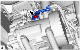
Remove the bolt and disconnect the bracket.
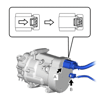
Slide the green-colored lock of the connector A as shown in the illustration to release it and disconnect the connector.
- CAUTION:
-
Make sure to wear insulating gloves.
- NOTICE:
-
Insulate the disconnected terminals and connector with insulating tape.
Disconnect the connector B.
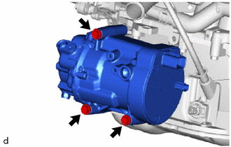
Remove the 3 bolts and compressor with motor assembly.