2ZR-FXE ENGINE MECHANICAL ENGINE UNIT INSTALLATION
PROCEDURE

 1.INSTALL WIRE HARNESS CLAMP BRACKET
Install the wire harness clamp bracket to the timing chain cover assembly with the bolt.
- Torque:
- 8.0 N*m (82 kgf*cm, 71 in.*lbf)
19500
2.INSTALL IGNITION COIL ASSEMBLY
12261
3.INSTALL VENTILATION HOSE
Install the ventilation hose to the PCV valve (ventilation valve sub-assembly) and slide the clip to secure it.
23250
4.INSTALL FUEL INJECTOR ASSEMBLY
23807V
5.INSTALL NO. 1 DELIVERY PIPE SPACER
23807
6.INSTALL FUEL DELIVERY PIPE SUB-ASSEMBLY
23818
7.INSTALL FUEL VAPOR FEED PIPE
Install the fuel vapor feed pipe to cylinder head cover sub-assembly with the 2 bolts.
- Torque:
- 10 N*m (102 kgf*cm, 7 ft.*lbf)
17650G
8.INSTALL PURGE VALVE (PURGE VSV)
1628A
9.INSTALL NO. 6 WATER BY-PASS PIPE
Install the No. 6 water by-pass pipe to the cylinder head sub-assembly with the 2 bolts.
- Torque:
- 21 N*m (214 kgf*cm, 15 ft.*lbf)
Connect the No. 6 water by-pass pipe to the water inlet sub-assembly and slide the clip to secure it.
16289
10.INSTALL WATER BY-PASS PIPE NO.5
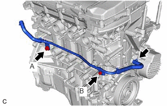
Install the No. 5 water by-pass pipe to the cylinder block sub-assembly with the 2 bolts.
- Torque:
- Bolt (A) : 21 N*m (214 kgf*cm, 15 ft.*lbf)
- Bolt (B) : 10 N*m (102 kgf*cm, 7 ft.*lbf)
Connect the No. 5 water by-pass pipe to the timing chain cover sub-assembly and slide the clip to secure it.
11452
11.INSTALL ENGINE OIL LEVEL DIPSTICK GUIDE
15301
12.INSTALL ENGINE OIL LEVEL DIPSTICK
17111
13.INSTALL INTAKE MANIFOLD
12261
14.CONNECT VENTILATION HOSE
17141
15.INSTALL EXHAUST MANIFOLD (TWC: Front Catalyst)
17167
16.INSTALL NO. 1 EXHAUST MANIFOLD HEAT INSULATOR
25733A
17.INSTALL NO. 1 PIPE (w/ Differential Pressure Sensor)
Temporarily install a new No. 1 pipe to the exhaust manifold with the nut.
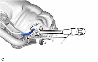
| *a | Torque Wrench Fulcrum Length |
Using a 14 mm union nut wrench, tighten the No. 1 pipe.
- Torque:
- Specified tightening torque : 30 N*m (306 kgf*cm, 22 ft.*lbf)
- HINT:
- ·
Calculate the torque wrench reading when changing the fulcrum length of the torque wrench.
Click hereGeneral>INTRODUCTION>REPAIR INSTRUCTION>PRECAUTION
·When using a union nut wrench (fulcrum length of 25 mm (0.984 in.)) + torque wrench (fulcrum length of 180 mm (7.09 in.)): 26.3 N*m (268 kgf*cm, 19 ft.*lbf).
Tighten the nut.
- Torque:
- 10 N*m (102 kgf*cm, 7 ft.*lbf)
25760
18.INSTALL VACUUM TRANSMITTING HOSE ASSEMBLY (w/ Differential Pressure Sensor)
Install the vacuum transmitting hose assembly to the No. 1 pipe and slide the clip to secure it.
25601L
19.TEMPORARILY INSTALL EGR VALVE ASSEMBLY WITH EGR COOLER
Install a new EGR cooler gasket.
Using an E8 "TORX" socket wrench, temporarily install the EGR valve assembly with EGR cooler with the 2 stud bolts.
- Torque:
- 9.5 N*m (97 kgf*cm, 84 in.*lbf)
Temporarily install the bolt and 4 nuts.
25610
20.TEMPORARILY INSTALL EGR PIPE ASSEMBLY
Install new EGR pipe gasket and inlet EGR gasket.
Temporarily install the EGR pipe assembly with the 4 bolts.
25601L
21.INSTALL EGR VALVE ASSEMBLY WITH EGR COOLER
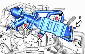

|
Bolt |

|
Nut |
Tighten the bolt and 4 nuts.
- Torque:
- Nut (A) : 21 N*m (214 kgf*cm, 15 ft.*lbf)
- Nut (B) : 26 N*m (265 kgf*cm, 19 ft.*lbf)
- Bolt : 21 N*m (214 kgf*cm, 15 ft.*lbf)
25610
22.INSTALL EGR PIPE ASSEMBLY
Tighten the bolt and 4 bolts.
- Torque:
- 8.5 N*m (87 kgf*cm, 75 in.*lbf)
16331
23.INSTALL WATER OUTLET (w/ Flow Shutting Valve (Water Valve))
Install the water outlet and a new water outlet gasket to the cylinder head sub-assembly with the 2 nuts.
- Torque:
- 28 N*m (286 kgf*cm, 21 ft.*lbf)
Connect the No. 9 water by-pass hose to the purge valve and slide the clip to secure it.
Connect the No. 4 water by-pass hose to the EGR valve assembly with EGR cooler and slide the clip to secure it.
Connect the No. 7 water by-pass hose to the No. 2 water by-pass hose and slide the clip to secure it.
16331
24.INSTALL WATER OUTLET (w/o Flow Shutting Valve (Water Valve))
Install the water outlet and a new water outlet gasket to the cylinder head sub-assembly with the 2 nuts.
- Torque:
- 28 N*m (286 kgf*cm, 21 ft.*lbf)
Connect the No. 9 water by-pass hose to the purge valve and slide the clip to secure it.
Connect the No. 4 water by-pass hose to the EGR valve assembly with EGR cooler and slide the clip to secure it.