Home › Audio / Visual / Telematics › AUDIO / VIDEO › AUDIO AND VISUAL SYSTEM (for Radio and Display Type with Dual Knob Type) › from 2022.01
RM32K0E _56 Audio / Visual / Telematics _061817 AUDIO / VIDEO _0524509 AUDIO AND VISUAL SYSTEM(for Radio and Display Type with Dual Knob Type) J

AUDIO / VIDEO  AUDIO AND VISUAL SYSTEM(for Radio and Display Type with Dual Knob Type)  Speaker Circuit  


DESCRIPTION

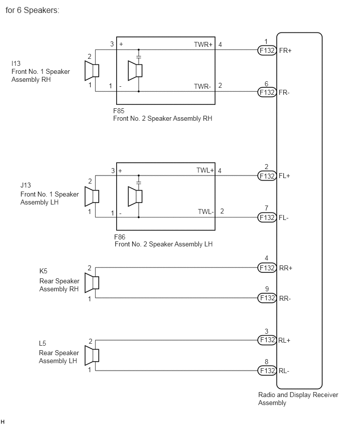
for 6 Speakers:

If there is a short in a speaker circuit, the radio and display receiver assembly detects it and stops output to the speakers.

Thus sound cannot be heard from the speakers even if there is no malfunction in the radio and display receiver assembly or speakers.


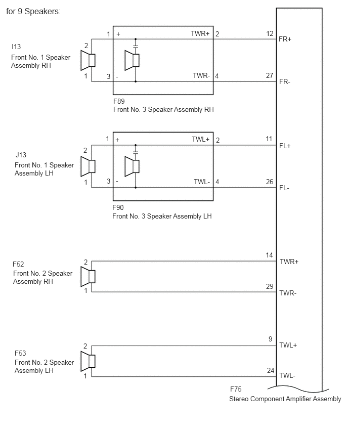
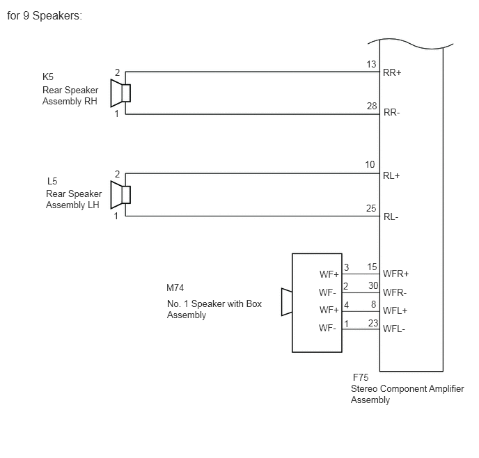
for 9 Speakers:

If there is a short in a speaker circuit, the stereo component amplifier assembly detects it and stops output to the speakers.

Thus sound cannot be heard from the speakers even if there is no malfunction in the stereo component amplifier assembly or speakers.


WIRING DIAGRAM
E425811E01
5.833,0.969 6.208,1.146 0.375,0.177 10 false FR+ 5.823,1.844 6.198,2.021 0.375,0.177 10 false FR- 5.823,3.583 6.198,3.76 0.375,0.177 10 false FL+ 5.823,4.458 6.198,4.635 0.375,0.177 10 false FL- 5.833,5.51 6.208,5.688 0.375,0.177 10 false RR+ 5.833,6.146 6.208,6.323 0.375,0.177 10 false RR- 5.813,7.021 6.188,7.198 0.375,0.177 10 false RL+ 5.823,7.656 6.198,7.833 0.375,0.177 10 false RL- 5.531,1.667 5.688,1.823 0.156,0.156 10 false 6 5.531,3.396 5.688,3.552 0.156,0.156 10 false 2 5.521,0.781 5.677,0.938 0.156,0.156 10 false 1 5.531,4.26 5.719,4.5 0.188,0.24 10 false 7 5.531,5.302 5.75,5.51 0.219,0.208 10 false 4 5.542,5.948 5.75,6.156 0.208,0.208 10 false 9 5.531,6.833 5.74,7.031 0.208,0.198 10 false 3 5.531,7.469 5.76,7.677 0.229,0.208 10 false 8 4.563,0.844 4.74,1.094 0.177,0.25 10 false 4 2.302,0.833 2.49,1.042 0.188,0.208 10 false 3 2.271,1.708 2.479,1.917 0.208,0.208 10 false 1 1.833,1.094 1.99,1.25 0.156,0.156 10 false 2 1.844,1.688 2.104,1.958 0.26,0.271 10 false 1 1.833,4.333 2,4.531 0.167,0.198 10 false 1 1.844,3.698 2.01,3.896 0.167,0.198 10 false 2 2.313,4.365 2.479,4.563 0.167,0.198 10 false 1 4.552,3.479 4.719,3.677 0.167,0.198 10 false 4 4.604,4.323 4.771,4.521 0.167,0.198 10 false 2 1.833,6.156 2,6.354 0.167,0.198 10 false 1 1.833,5.51 2,5.708 0.167,0.198 10 false 2 1.833,7.635 2,7.833 0.167,0.198 10 false 1 1.854,7.042 2.021,7.24 0.167,0.198 10 false 2 4.563,1.698 4.76,1.969 0.198,0.271 10 false 2 2.323,3.479 2.49,3.677 0.167,0.198 10 false 3 0.24,1.406 1.521,2.052 1.281,0.646 10 false Front No. 1 Speaker Assembly RH 2.365,2.385 4.802,2.656 2.438,0.271 10 false Front No. 2 Speaker Assembly RH 5.427,0.969 5.75,1.156 0.323,0.188 10 false F132 5.427,1.844 5.781,2.01 0.354,0.167 10 false F132 5.427,3.594 5.76,3.833 0.333,0.24 10 false F132 5.427,4.458 5.76,4.625 0.333,0.167 10 false F132 5.427,5.51 5.76,5.677 0.333,0.167 10 false F132 5.438,6.135 5.771,6.354 0.333,0.219 10 false F132 5.438,7.01 6.323,7.198 0.885,0.188 10 false F132 5.438,7.656 5.771,7.906 0.333,0.25 10 false F132 2.396,5.01 4.917,5.229 2.521,0.219 10 false Front No. 2 Speaker Assembly LH 0.427,3.969 1.677,4.5 1.25,0.531 10 false Front No. 1 Speaker Assembly LH 0.823,5.781 1.719,6.323 0.896,0.542 10 false Rear Speaker Assembly RH 0.813,7.281 1.667,7.688 0.854,0.406 10 false Rear Speaker Assembly LH 2.365,2.229 2.74,2.406 0.375,0.177 10 false F85 0.24,1.24 0.615,1.417 0.375,0.177 10 false I13 0.427,3.781 0.802,3.958 0.375,0.177 10 false J13 2.385,4.865 2.76,5.042 0.375,0.177 10 false F86 0.823,5.573 1.198,5.75 0.375,0.177 10 false K5 0.813,7.083 1.188,7.26 0.375,0.177 10 false L5 2.49,0.833 2.646,0.99 0.156,0.156 10 false + 2.469,3.479 2.625,3.635 0.156,0.156 10 false + 2.49,1.708 2.646,1.865 0.156,0.156 10 false - 2.49,4.365 2.646,4.521 0.156,0.156 10 false - 4.104,3.469 4.521,3.646 0.417,0.177 10 false TWL+ 4.135,4.333 4.521,4.531 0.385,0.198 10 false TWL- 4.052,0.844 4.469,1.021 0.417,0.177 10 false TWR+ 4.052,1.719 4.469,1.896 0.417,0.177 10 false TWR- 5.396,8.156 7.104,8.542 1.708,0.385 10 false Radio and Display Receiver Assembly 0.115,0.104 2.875,0.344 2.76,0.24 12 false for 6 Speakers:

E425812E01
4.719,8.125 7.156,8.323 2.438,0.198 10 false Stereo Component Amplifier Assembly 0.302,7.375 1.563,7.823 1.26,0.448 10 false Front No. 2 Speaker Assembly LH 0.271,5.542 1.531,6.021 1.26,0.479 10 false Front No. 2 Speaker Assembly RH 0.302,3.313 1.573,3.729 1.271,0.417 10 false Front No. 1 Speaker Assembly LH 0.229,1.094 1.49,1.51 1.26,0.417 10 false Front No. 1 Speaker Assembly RH 2.333,2.167 5.385,2.448 3.052,0.281 10 false Front No. 3 Speaker Assembly RH 2.313,4.365 5.365,4.646 3.052,0.281 10 false Front No. 3 Speaker Assembly LH 4.74,7.927 5.198,8.125 0.458,0.198 10 false F75 2.313,4.188 2.771,4.385 0.458,0.198 10 false F90 2.333,2 2.792,2.198 0.458,0.198 10 false F89 5.75,7.646 6.208,7.844 0.458,0.198 10 false TWL- 5.75,7.021 6.208,7.219 0.458,0.198 10 false TWL+ 5.75,5.948 6.208,6.146 0.458,0.198 10 false TWR- 5.76,5.302 6.219,5.5 0.458,0.198 10 false TWR+ 5.75,3.781 6.208,3.979 0.458,0.198 10 false FL- 5.75,2.917 6.208,3.115 0.458,0.198 10 false FL+ 5.75,1.594 6.208,1.792 0.458,0.198 10 false FR- 5.74,0.719 6.198,0.917 0.458,0.198 10 false FR+ 0.302,7.188 0.76,7.385 0.458,0.198 10 false F53 0.26,5.354 0.719,5.552 0.458,0.198 10 false F52 0.323,3.104 0.781,3.302 0.458,0.198 10 false J13 0.24,0.875 0.698,1.073 0.458,0.198 10 false I13 1.729,1.479 2.188,1.677 0.458,0.198 10 false 1 2.198,0.615 2.656,0.813 0.458,0.198 10 false 1 1.729,3.667 2.115,3.917 0.385,0.25 10 false 1 2.177,2.771 2.563,3.021 0.385,0.25 10 false 1 1.729,5.896 2.115,6.146 0.385,0.25 10 false 1 1.719,7.656 2.104,7.906 0.385,0.25 10 false 1 1.719,7.042 2.104,7.292 0.385,0.25 10 false 2 1.729,5.313 2.115,5.563 0.385,0.25 10 false 2 1.719,3.01 2.104,3.26 0.385,0.25 10 false 2 1.74,0.854 2.125,1.104 0.385,0.25 10 false 2 4.438,0.615 4.823,0.865 0.385,0.25 10 false 2 4.448,2.802 4.833,3.052 0.385,0.25 10 false 2 2.198,3.646 2.583,3.896 0.385,0.25 10 false 3 2.198,1.49 2.583,1.74 0.385,0.25 10 false 3 4.427,1.479 4.813,1.729 0.385,0.25 10 false 4 4.438,3.656 4.823,3.906 0.385,0.25 10 false 4 3.927,0.604 5.031,0.792 1.104,0.188 10 false TWR+ 3.969,1.469 5.073,1.656 1.104,0.188 10 false TWR- 3.948,2.781 5.052,2.969 1.104,0.188 10 false TWL+ 3.99,3.656 5.094,3.844 1.104,0.188 10 false TWL- 2.396,0.615 2.854,0.813 0.458,0.198 10 false + 2.375,2.792 2.833,2.99 0.458,0.198 10 false + 2.385,1.49 2.844,1.688 0.458,0.198 10 false - 2.385,3.635 2.844,3.833 0.458,0.198 10 false - 5.479,0.604 5.865,0.854 0.385,0.25 10 false 12 5.479,1.469 5.865,1.719 0.385,0.25 10 false 27 5.469,2.771 5.854,3.021 0.385,0.25 10 false 11 5.479,3.656 5.865,3.906 0.385,0.25 10 false 26 5.469,5.167 5.854,5.417 0.385,0.25 10 false 14 5.479,5.813 5.865,6.063 0.385,0.25 10 false 29 5.531,6.896 5.917,7.146 0.385,0.25 10 false 9 5.5,7.542 5.885,7.792 0.385,0.25 10 false 24 0.125,0.125 2.885,0.365 2.76,0.24 12 false for 9 Speakers:

E425790E03
0.104,0.125 2.865,0.365 2.76,0.24 12 false for 9 Speakers: 5.281,5.563 5.74,5.76 0.458,0.198 10 false F75 5.25,5.729 6.979,6.396 1.729,0.667 10 false Stereo Component Amplifier Assembly 5.729,1 6.188,1.198 0.458,0.198 10 false RR+ 5.74,1.594 6.198,1.792 0.458,0.198 10 false RR- 5.729,2.542 6.188,2.74 0.458,0.198 10 false RL+ 5.74,3.156 6.198,3.354 0.458,0.198 10 false RL- 5.729,4.01 6.24,4.229 0.51,0.219 10 false WFR+ 5.729,4.292 6.24,4.51 0.51,0.219 10 false WFR- 5.729,4.563 6.24,4.781 0.51,0.219 10 false WFL+ 5.729,4.833 6.24,5.052 0.51,0.219 10 false WFL- 2.49,4.219 2.948,4.417 0.458,0.198 10 false M74 2.5,4.458 3.99,5.104 1.49,0.646 10 false No. 1 Speaker with Box Assembly 4.781,4.021 5.292,4.24 0.51,0.219 10 false WF+ 4.781,4.552 5.292,4.771 0.51,0.219 10 false WF+ 4.771,4.292 5.281,4.51 0.51,0.219 10 false WF- 4.771,4.823 5.281,5.042 0.51,0.219 10 false WF- 5.479,0.875 5.792,1.073 0.313,0.198 10 false 13 5.49,1.5 5.802,1.698 0.313,0.198 10 false 28 5.458,2.375 5.771,2.573 0.313,0.198 10 false 10 5.479,3.031 5.792,3.229 0.313,0.198 10 false 25 5.49,3.906 5.802,4.104 0.313,0.198 10 false 15 5.51,4.188 5.823,4.385 0.313,0.198 10 false 30 5.51,4.75 5.823,4.948 0.313,0.198 10 false 23 5.552,4.469 5.792,4.688 0.24,0.219 10 false 8 5.146,4.76 5.458,4.958 0.313,0.198 10 false 1 5.146,4.479 5.458,4.677 0.313,0.198 10 false 4 5.135,4.198 5.448,4.396 0.313,0.198 10 false 2 5.146,3.917 5.458,4.115 0.313,0.198 10 false 3 0.635,1.063 1.094,1.26 0.458,0.198 10 false K5 0.635,1.26 1.521,1.896 0.885,0.635 10 false Rear Speaker Assembly RH 0.708,2.625 1.167,2.823 0.458,0.198 10 false L5 0.688,2.813 1.573,3.448 0.885,0.635 10 false Rear Speaker Assembly LH 1.708,1.615 2.021,1.813 0.313,0.198 10 false 1 1.698,3.146 2.01,3.344 0.313,0.198 10 false 1 1.719,2.521 2.031,2.719 0.313,0.198 10 false 2 1.719,1 2.031,1.198 0.313,0.198 10 false 2


PROCEDURE

1.CONFIRM MODEL
a.

Choose the model to be inspected.

Result:
Result Proceed to
for 6 Speakers A
for 9 Speakers B


A

2.CHECK SPEAKER (OPERATION CHECK)

B

8.CHECK SPEAKER (OPERATION CHECK)
2.CHECK SPEAKER (OPERATION CHECK)
a.
E268474

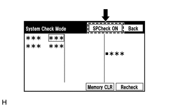
Enter the "System Check Mode" screen. Refer to Check Speaker in Operation Check.

Click hereAudio / Visual / Telematics>AUDIO / VIDEO>AUDIO AND VISUAL SYSTEM (for Radio and Display Type with Dual Knob Type)>OPERATION CHECK


b.

Perform the operation check above and determine the speaker that is not operating.

Result:
Not Operating Speaker Proceed to
Front No. 1 speaker assembly or front No. 2 speaker assembly A
Rear speaker assembly B


HINT:

If sound cannot be heard from any speaker, inspect all of them.


A

3.CHECK HARNESS AND CONNECTOR (RADIO AND DISPLAY RECEIVER ASSEMBLY - FRONT NO. 1 SPEAKER ASSEMBLY - FRONT NO. 2 SPEAKER ASSEMBLY)

B

6.CHECK HARNESS AND CONNECTOR (RADIO AND DISPLAY RECEIVER ASSEMBLY - REAR SPEAKER ASSEMBLY)
3.CHECK HARNESS AND CONNECTOR (RADIO AND DISPLAY RECEIVER ASSEMBLY - FRONT NO. 1 SPEAKER ASSEMBLY - FRONT NO. 2 SPEAKER ASSEMBLY)
a.

Disconnect the F132 radio and display receiver assembly connector.


b.

Disconnect the I13 and J13 front No. 1 speaker assembly connectors.


c.

Disconnect the F85 and F86 front No. 2 speaker assembly connectors.


d.

Measure the resistance according to the value(s) in the table below.

Standard Resistance:
Tester Connection Condition Specified Condition
F132-1 (FR+) - F85-4 (TWR+) Always Below 1 Ω
F132-6 (FR-) - F85-2 (TWR-) Always Below 1 Ω
F132-2 (FL+) - F86-4 (TWL+) Always Below 1 Ω
F132-7 (FL-) - F86-2 (TWL-) Always Below 1 Ω
I13-2 - F85-3 (+) Always Below 1 Ω
I13-1 - F85-1 (-) Always Below 1 Ω
J13-2 - F86-3 (+) Always Below 1 Ω
J13-1 - F86-1 (-) Always Below 1 Ω
F132-1 (FR+) or F85-4 (TWR+) - Body ground Always 10 kΩ or higher
F132-6 (FR-) or F85-2 (TWR-) - Body ground Always 10 kΩ or higher
F132-2 (FL+) or F86-4 (TWL+) - Body ground Always 10 kΩ or higher
F132-7 (FL-) or F86-2 (TWL-) - Body ground Always 10 kΩ or higher
I13-2 or F85-3 (+) - Body ground Always 10 kΩ or higher
I13-1 or F85-1 (-) - Body ground Always 10 kΩ or higher
J13-2 or F86-3 (+) - Body ground Always 10 kΩ or higher
J13-1 or F86-1 (-) - Body ground Always 10 kΩ or higher


Result:
Proceed to
OK
NG


OK

4.INSPECT FRONT NO. 2 SPEAKER ASSEMBLY

NG

REPAIR OR REPLACE HARNESS OR CONNECTOR

4.INSPECT FRONT NO. 2 SPEAKER ASSEMBLY
a.

Remove the front No. 2 speaker assembly.

Click hereAudio / Visual / Telematics>AUDIO / VIDEO>INSTRUMENT PANEL SPEAKER>REMOVAL


b.

Inspect the front No. 2 speaker assembly.

Click hereAudio / Visual / Telematics>AUDIO / VIDEO>INSTRUMENT PANEL SPEAKER>INSPECTION


c.

Check that the malfunction disappears when a new or known good front No. 2 speaker assembly is installed.

OK:

Malfunction disappears.


Result:
Proceed to
OK
NG


OK

END

NG

5.INSPECT FRONT NO. 1 SPEAKER ASSEMBLY
a.

Remove the front No. 1 speaker assembly.

Click hereAudio / Visual / Telematics>AUDIO / VIDEO>FRONT DOOR SPEAKER>REMOVAL


b.

Inspect the front No. 1 speaker assembly.

Click hereAudio / Visual / Telematics>AUDIO / VIDEO>FRONT DOOR SPEAKER>INSPECTION


Result:
Proceed to
OK
NG


OK

NG

REPLACE FRONT NO. 1 SPEAKER ASSEMBLY

6.CHECK HARNESS AND CONNECTOR (RADIO AND DISPLAY RECEIVER ASSEMBLY - REAR SPEAKER ASSEMBLY)
a.

Disconnect the F132 radio and display receiver assembly connector.


b.

Disconnect the L5 and K5 rear speaker assembly connectors.


c.

Measure the resistance according to the value(s) in the table below.

Standard Resistance:
Tester Connection Condition Specified Condition
F132-4 (RR+) - K5-2 Always Below 1 Ω
F132-9 (RR-) - K5-1 Always Below 1 Ω
F132-3 (RL+) - L5-2 Always Below 1 Ω
F132-8 (RL-) - L5-1 Always Below 1 Ω
F132-4 (RR+) or K5-2 - Body ground Always 10 kΩ or higher
F132-9 (RR-) or K5-1 - Body ground Always 10 kΩ or higher
F132-3 (RL+) or L5-2 - Body ground Always 10 kΩ or higher
F132-8 (RL-) or L5-1 - Body ground Always 10 kΩ or higher


Result:
Proceed to
OK
NG


OK

7.INSPECT REAR SPEAKER ASSEMBLY

NG

REPAIR OR REPLACE HARNESS OR CONNECTOR

7.INSPECT REAR SPEAKER ASSEMBLY
a.

Remove the rear speaker assembly.

Click hereAudio / Visual / Telematics>AUDIO / VIDEO>REAR DOOR SPEAKER>REMOVAL


b.

Inspect the rear speaker assembly.

Click hereAudio / Visual / Telematics>AUDIO / VIDEO>REAR DOOR SPEAKER>INSPECTION


Result:
Proceed to
OK
NG


OK

NG

8.CHECK SPEAKER (OPERATION CHECK)
a.
E268474

Enter the "System Check Mode" screen. Refer to Check Speaker in Operation Check.

Click hereAudio / Visual / Telematics>AUDIO / VIDEO>AUDIO AND VISUAL SYSTEM (for Radio and Display Type with Dual Knob Type)>OPERATION CHECK


b.

Perform the operation check above and determine the speaker that is not operating.

Result:
Not Operating Speaker Proceed to
Front No. 1 speaker assembly or front No. 3 speaker assembly A
Front No. 2 speaker assembly B
Rear speaker assembly C
No. 1 speaker with box assembly D


HINT:

If sound cannot be heard from any speaker, inspect all of them.


A

9.CHECK HARNESS AND CONNECTOR (STEREO COMPONENT AMPLIFIER ASSEMBLY - FRONT NO. 1 SPEAKER ASSEMBLY - FRONT NO. 3 SPEAKER ASSEMBLY)

B

12.CHECK HARNESS AND CONNECTOR (STEREO COMPONENT AMPLIFIER ASSEMBLY - FRONT NO. 2 SPEAKER ASSEMBLY)

C

14.CHECK HARNESS AND CONNECTOR (STEREO COMPONENT AMPLIFIER ASSEMBLY - REAR SPEAKER ASSEMBLY)

D

16.CHECK HARNESS AND CONNECTOR (STEREO COMPONENT AMPLIFIER ASSEMBLY - NO. 1 SPEAKER WITH BOX ASSEMBLY)
9.CHECK HARNESS AND CONNECTOR (STEREO COMPONENT AMPLIFIER ASSEMBLY - FRONT NO. 1 SPEAKER ASSEMBLY - FRONT NO. 3 SPEAKER ASSEMBLY)
a.

Disconnect the F75 stereo component amplifier assembly connector.


b.

Disconnect the I13 and J13 front No. 1 speaker assembly connectors.


c.

Disconnect the F89 and F90 front No. 3 speaker assembly connectors.


d.

Measure the resistance according to the value(s) in the table below.

Standard Resistance:
Tester Connection Condition Specified Condition
F75-12 (FR+) - F89-2 (TWR+) Always Below 1 Ω
F75-27 (FR-) - F89-4 (TWR-) Always Below 1 Ω
F75-11 (FL+) - F90-2 (TWL+) Always Below 1 Ω
F75-26 (FL-) - F90-4 (TWL-) Always Below 1 Ω
I13-2 - F89-1 (+) Always Below 1 Ω
I13-1 - F89-3 (-) Always Below 1 Ω
J13-2 - F90-1 (+) Always Below 1 Ω
J13-1 - F90-3 (-) Always Below 1 Ω
F75-12 (FR+) or F89-2 (TWR+) - Body ground Always 10 kΩ or higher
F75-27 (FR-) or F89-4 (TWR-) - Body ground Always 10 kΩ or higher
F75-11 (FL+) or F90-2 (TWL+) - Body ground Always 10 kΩ or higher
F75-26 (FL-) or F90-4 (TWL-) - Body ground Always 10 kΩ or higher
I13-2 or F89-1 (+) - Body ground Always 10 kΩ or higher
I13-1 or F89-3 (-) - Body ground Always 10 kΩ or higher
J13-2 or F90-1 (+) - Body ground Always 10 kΩ or higher
J13-1 or F90-3 (-) - Body ground Always 10 kΩ or higher


Result:
Proceed to
OK
NG


OK

10.INSPECT FRONT NO. 3 SPEAKER ASSEMBLY

NG

REPAIR OR REPLACE HARNESS OR CONNECTOR

10.INSPECT FRONT NO. 3 SPEAKER ASSEMBLY
a.

Remove the front No. 3 speaker assembly.

Click hereAudio / Visual / Telematics>AUDIO / VIDEO>PILLAR SPEAKER>REMOVAL


b.

Inspect the front No. 3 speaker assembly.

Click hereAudio / Visual / Telematics>AUDIO / VIDEO>PILLAR SPEAKER>INSPECTION


c.

Check that the malfunction disappears when a new or known good front No. 3 speaker assembly is installed.

OK:

Malfunction disappears.


Result:
Proceed to
OK
NG


OK

END

NG

11.INSPECT FRONT NO. 1 SPEAKER ASSEMBLY
a.

Remove the front No. 1 speaker assembly.

Click hereAudio / Visual / Telematics>AUDIO / VIDEO>FRONT DOOR SPEAKER>REMOVAL


b.

Inspect the front No. 1 speaker assembly.

Click hereAudio / Visual / Telematics>AUDIO / VIDEO>FRONT DOOR SPEAKER>INSPECTION


Result:
Proceed to
OK
NG


OK

NG

REPLACE FRONT NO. 1 SPEAKER ASSEMBLY

12.CHECK HARNESS AND CONNECTOR (STEREO COMPONENT AMPLIFIER ASSEMBLY - FRONT NO. 2 SPEAKER ASSEMBLY)
a.

Disconnect the F75 stereo component amplifier assembly connector.


b.

Disconnect the F52 and F53 front No. 2 speaker assembly connectors.


c.

Measure the resistance according to the value(s) in the table below.

Standard Resistance:
Tester Connection Condition Specified Condition
F75-14 (TWR+) - F52-2 Always Below 1 Ω
F75-29 (TWR-) - F52-1 Always Below 1 Ω
F75-9 (TWL+) - F53-2 Always Below 1 Ω
F75-24 (TWL-) - F53-1 Always Below 1 Ω
F75-14 (TWR+) or F52-2 - Body ground Always 10 kΩ or higher
F75-29 (TWR-) or F52-1 - Body ground Always 10 kΩ or higher
F75-9 (TWL+) or F53-2 - Body ground Always 10 kΩ or higher
F75-24 (TWL-) or F53-1 - Body ground Always 10 kΩ or higher


Result:
Proceed to
OK
NG


OK

13.INSPECT FRONT NO. 2 SPEAKER ASSEMBLY

NG

REPAIR OR REPLACE HARNESS OR CONNECTOR

13.INSPECT FRONT NO. 2 SPEAKER ASSEMBLY
a.

Remove the front No. 2 speaker assembly.

Click hereAudio / Visual / Telematics>AUDIO / VIDEO>INSTRUMENT PANEL SPEAKER>REMOVAL


b.

Inspect the front No. 2 speaker assembly.

Click hereAudio / Visual / Telematics>AUDIO / VIDEO>INSTRUMENT PANEL SPEAKER>INSPECTION


Result:
Proceed to
OK
NG


OK

NG

REPLACE FRONT NO. 2 SPEAKER ASSEMBLY

14.CHECK HARNESS AND CONNECTOR (STEREO COMPONENT AMPLIFIER ASSEMBLY - REAR SPEAKER ASSEMBLY)
a.

Disconnect the F75 stereo component amplifier assembly connector.


b.

Disconnect the L5 and K5 rear speaker assembly connectors.


c.

Measure the resistance according to the value(s) in the table below.

Standard Resistance:
Tester Connection Condition Specified Condition
F75-13 (RR+) - K5-2 Always Below 1 Ω
F75-28 (RR-) - K5-1 Always Below 1 Ω
F75-10 (RL+) - L5-2 Always Below 1 Ω
F75-25 (RL-) - L5-1 Always Below 1 Ω
F75-13 (RR+) or K5-2 - Body ground Always 10 kΩ or higher
F75-28 (RR-) or K5-1 - Body ground Always 10 kΩ or higher
F75-10 (RL+) or L5-2 - Body ground Always 10 kΩ or higher
F75-25 (RL-) or L5-1 - Body ground Always 10 kΩ or higher


Result:
Proceed to
OK
NG


OK

15.INSPECT REAR SPEAKER ASSEMBLY

NG

REPAIR OR REPLACE HARNESS OR CONNECTOR

15.INSPECT REAR SPEAKER ASSEMBLY
a.

Remove the rear speaker assembly.

Click hereAudio / Visual / Telematics>AUDIO / VIDEO>REAR DOOR SPEAKER>REMOVAL


b.

Inspect the rear speaker assembly.

Click hereAudio / Visual / Telematics>AUDIO / VIDEO>REAR DOOR SPEAKER>INSPECTION


Result:
Proceed to
OK
NG


OK

NG

16.CHECK HARNESS AND CONNECTOR (STEREO COMPONENT AMPLIFIER ASSEMBLY - NO. 1 SPEAKER WITH BOX ASSEMBLY)
a.

Disconnect the F75 stereo component amplifier assembly connector.


b.

Disconnect the M74 No. 1 speaker with box assembly connector.


c.

Measure the resistance according to the value(s) in the table below.

Standard Resistance:
Tester Connection Condition Specified Condition
F75-15 (WFR+) - M74-3 (WF+) Always Below 1 Ω
F75-30 (WFR-) - M74-2 (WF-) Always Below 1 Ω
F75-8 (WFL+) - M74-4 (WF+) Always Below 1 Ω
F75-23 (WFL-) - M74-1 (WF-) Always Below 1 Ω
F75-15 (WFR+) or M74-3 (WF+) - Body ground Always 10 kΩ or higher
F75-30 (WFR-) or M74-2 (WF-) - Body ground Always 10 kΩ or higher
F75-8 (WFL+) or M74-4 (WF+) - Body ground Always 10 kΩ or higher
F75-23 (WFL-) or M74-1 (WF-) - Body ground Always 10 kΩ or higher


Result:
Proceed to
OK
NG


OK

17.INSPECT NO. 1 SPEAKER WITH BOX ASSEMBLY

NG

REPAIR OR REPLACE HARNESS OR CONNECTOR

17.INSPECT NO. 1 SPEAKER WITH BOX ASSEMBLY
a.

Remove the No. 1 speaker with box assembly.

Click hereAudio / Visual / Telematics>AUDIO / VIDEO>QUARTER TRIM SPEAKER>REMOVAL


b.

Inspect the No. 1 speaker with box assembly.

Click hereAudio / Visual / Telematics>AUDIO / VIDEO>QUARTER TRIM SPEAKER>INSPECTION


Result:
Proceed to
OK
NG


OK

NG

REPLACE NO. 1 SPEAKER WITH BOX ASSEMBLY