K313F MULTIDRIVE / CVT CONTINUOUSLY VARIABLE TRANSAXLE SYSTEM P070513 Transmission Range Sensor "A" Circuit Open P070562 Transmission Range Sensor "A" Signal Compare Failure
DESCRIPTION
The park/neutral position switch and shift lock control unit assembly (transmission control switch) detect the shift lever position and send signals to the ECM.
| DTC No. | Detection Item | DTC Detection Condition | Trouble Area | MIL | Memory | Note |
|---|---|---|---|---|---|---|
| P070513 | Transmission Range Sensor "A" Circuit Open | When the ignition switch is ON and the battery voltage is 10.5 V or more, all signals are OFF simultaneously for NSW, P, R, N and D for 60 seconds (2 trip detection logic). | ·
Wire harness or connector ·
Park/neutral position switch ·
Shift lock control unit assembly (Transmission control switch) ·
ECM |
Comes on | DTC stored | SAE Code:
P0705 |
| P070562 | Transmission Range Sensor "A" Signal Compare Failure | When the ignition switch is ON and the battery voltage is 10.5 V or more, either one of the following conditions is met (2 trip detection logic):
·
2 or more signals are ON simultaneously for 2 seconds or more for (NSW, P, N), R, D input signals. ·
When the S signal (M position switch signal) is ON, any of the NSW, P, R, N input signals is ON simultaneously for 2 seconds or more. |
·
Wire harness or connector ·
Park/neutral position switch ·
Shift lock control unit assembly (Transmission control switch) ·
ECM |
Comes on | DTC stored | SAE Code:
P0705 |
| Vehicle Condition | |||
|---|---|---|---|
| Pattern 1 | Pattern 2 | ||
| Diagnostic Condition | Ignition switch ON and the battery voltage is 10.5 V or more | ○ | ○ |
| Malfunction Condition | 2 or more signals are ON simultaneously for (NSW, P, N), R, D input signals. | ○ | - |
| When the S signal (M position switch signal) is ON, any of the NSW, P, R, N input signals is ON simultaneously. | - | ○ | |
| Duration | 2 seconds or more | 2 seconds or more | |
| Detection Logic | 2 trip detection logic | 2 trip detection logic | |
- HINT:
-
This DTC is output when either of the above detection patterns is met.
MONITOR DESCRIPTION
This DTC indicates a problem with the park/neutral position switch or the wire harness of the park/neutral position switch circuit.
The park/neutral position switch detects the shift lever position and sends a signal to the ECM. For safety, the park/neutral position switch detects the shift lever position so that the engine can be started only when the shift lever is in P or N.
WIRING DIAGRAM
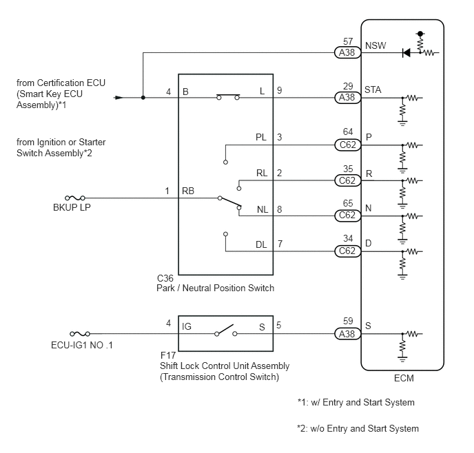
CAUTION / NOTICE / HINT
- NOTICE:
- ·
Perform initialization when parts related to the continuously variable transaxle are replaced.
Click hereDrivetrain>K313F (MULTIDRIVE / CVT)>CONTINUOUSLY VARIABLE TRANSAXLE SYSTEM>INITIALIZATION
·Check that no DTCs are stored after performing initialization.
Click hereDrivetrain>K313F (MULTIDRIVE / CVT)>CONTINUOUSLY VARIABLE TRANSAXLE SYSTEM>DTC CHECK / CLEAR
·Inspect the fuses for circuits related to this system before performing the following inspection procedure.
- HINT:
-
After performing repair, clear the DTCs and perform the following procedure to check that DTCs are not output.
- 1.
Turn the ignition switch to ON.
2.Wait with the shift lever in each position (P, R, N and D) for 60 seconds or more each.
3.Turn the ignition switch off.
4.Perform steps (1) through (2) again.
5.Check for DTCs again.
Click hereDrivetrain>K313F (MULTIDRIVE / CVT)>CONTINUOUSLY VARIABLE TRANSAXLE SYSTEM>DTC CHECK / CLEAR
PROCEDURE
Connect the GTS to the DLC3.
Turn the ignition switch to ON.
Turn the GTS on.
Enter the following menus: Powertrain / Transmission / Data List.
- Powertrain > Transmission > Data List
-
Tester Display Neutral Position SW Shift SW Status (P Range) Shift SW Status (R Range) Shift SW Status (N Range) Shift SW Status (D Range) - 50003 373 20,15,14,13,28
According to the display on the GTS, read the Data List.
- Powertrain > Transmission > Data List
-
Tester Display Measurement Item Range Normal Condition Diagnostic Note Neutral Position SW Park/neutral position switch status OFF or ON ·OFF: Shift lever not in P or N
·ON: Shift lever in P or N
When the shift lever position displayed on the GTS differs from the actual position, the adjustment of the park/neutral position switch or shift cable may be incorrect. Shift SW Status (P Range) Park/neutral position switch status OFF or ON ·OFF: Shift lever not in P
·ON: Shift lever in P
When the shift lever position displayed on the GTS differs from the actual position, the adjustment of the park/neutral position switch or shift cable may be incorrect. Shift SW Status (R Range) Park/neutral position switch status OFF or ON ·OFF: Shift lever not in R
·ON: Shift lever in R
When the shift lever position displayed on the GTS differs from the actual position, the adjustment of the park/neutral position switch or shift cable may be incorrect. Shift SW Status (N Range) Park/neutral position switch status OFF or ON ·OFF: Shift lever not in N
·ON: Shift lever in N
When the shift lever position displayed on the GTS differs from the actual position, the adjustment of the park/neutral position switch or shift cable may be incorrect. Shift SW Status (D Range) Park/neutral position switch status OFF or ON ·OFF: Shift lever not in D
·ON: Shift lever in D
When the shift lever position displayed on the GTS differs from the actual position, the adjustment of the park/neutral position switch or shift cable may be incorrect.
- Result:
Result Proceed to Data List value is normal A Data List value is not normal B
A
B
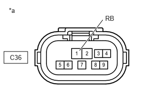
| *a | Front view of wire harness connector
(to Park/Neutral Position Switch) |
Disconnect the park/neutral position switch connector.
Measure the voltage according to the value(s) in the table below.
- Standard Voltage:
Tester Connection Switch Condition Specified Condition C36-1 (RB) - Body ground Ignition switch ON 11 to 14 V C36-1 (RB) - Body ground Ignition switch off Below 1 V
Connect the park/neutral position switch connector.
- Result:
Proceed to OK NG
OK
NG
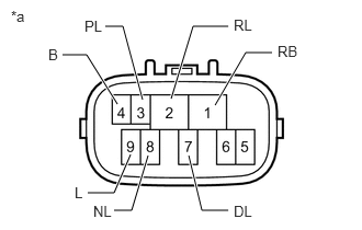
| *a | Component without harness connected
(Park/Neutral Position Switch) |
Disconnect the C36 park/neutral position switch connector.
Measure the resistance according to the value(s) in the table below.
- Standard Resistance:
Tester Connection Condition Specified Condition 4 (B) - 9 (L) Shift lever in P or N Below 1 Ω Shift lever not in P or N 10 kΩ or higher 1 (RB) - 3 (PL) Shift lever in P Below 1 Ω Shift lever not in P 10 kΩ or higher 1 (RB) - 2 (RL) Shift lever in R Below 1 Ω Shift lever not in R 10 kΩ or higher 1 (RB) - 8 (NL) Shift lever in N Below 1 Ω Shift lever not in N 10 kΩ or higher 1 (RB) - 7 (DL) Shift lever in D Below 1 Ω Shift lever not in D 10 kΩ or higher
Connect the C36 park/neutral position switch connector.
- Result:
Proceed to OK NG
OK
NG
Disconnect the C36 park/neutral position switch connector.
Disconnect the A38 and C62 ECM connectors.
Measure the resistance according to the value(s) in the table below.
- Standard Resistance:
Tester Connection Condition Specified Condition C36-3 (PL) - C62-64 (P) Always Below 1 Ω C36-2 (RL) - C62-35 (R) Always Below 1 Ω C36-8 (NL) - C62-65 (N) Always Below 1 Ω C36-7 (DL) - C62-34 (D) Always Below 1 Ω C36-4 (B) - A38-57 (NSW) Always Below 1 Ω C36-3 (PL) or C62-64 (P) - Body ground and other terminals Always 10 kΩ or higher C36-2 (RL) or C62-35 (R) - Body ground and other terminals Always 10 kΩ or higher C36-8 (NL) or C62-65 (N) - Body ground and other terminals Always 10 kΩ or higher C36-7 (DL) or C62-34 (D) - Body ground and other terminals Always 10 kΩ or higher C36-4 (B) or A38-57 (NSW) - Body ground and other terminals Always 10 kΩ or higher
Connect the A38 and C62 ECM connectors.
Connect the C36 park/neutral position switch connector.
- Result:
Proceed to OK NG
OK
NG
Replace the ECM.
Click hereEngine / Hybrid System>8NR-FTS (ENGINE CONTROL)>ECM>REMOVAL
- Result:
Proceed to NEXT
NEXT