3ZR-FAE ENGINE MECHANICAL CAMSHAFT REMOVAL
CAUTION / NOTICE / HINT
The necessary procedures (adjustment, calibration, initialization, or registration) that must be performed after parts are removed, installed, or replaced during the camshaft removal/installation are shown below.
| Replacement Part or Procedure | Necessary Procedure | Effect/Inoperative when not Performed | Link |
|---|---|---|---|
| Disconnect cable from negative battery terminal | Perform steering sensor zero point calibration | Toyota parking assist-sensor system*1 | ( ) |
| Simple intelligent parking assist system*1 | |||
| Initialize back door lock | Power door lock control system | ()
|
|
·
Replacement of camshaft timing gear assembly ·
Replacement of camshaft timing exhaust gear assembly ·
Replacement of camshaft ·
Replacement of No. 2 camshaft |
Inspection After Repair | ·
Poor idle, etc. ·
Engine start function, etc. |
()
|
| Replacement of CVT fluid | ATF thermal degradation estimate reset | The value of the Data List item "ATF thermal Degradation Estimate" is not estimated correctly | ()
|
| Front wheel alignment adjustment | Perform the following procedures in the order shown:
1.
Clear zero point calibration data and store system information 2.
Perform yaw rate and acceleration sensor zero point calibration and store system information |
·
VSC disabled or malfunctions ·
DTCs are stored ·
Slip indicator light illuminates ·
ABS warning light illuminates |
()
|
*1: When performing learning using the GTS.
Click hereAudio / Visual / Telematics>PARK ASSIST / MONITORING>TOYOTA PARKING ASSIST-SENSOR SYSTEM>CALIBRATION
PROCEDURE

 13506
1.REMOVE CHAIN SUB-ASSEMBLY
13050
2.INSPECT CAMSHAFT TIMING GEAR ASSEMBLY
Inspect the lock of the camshaft timing gear assembly.
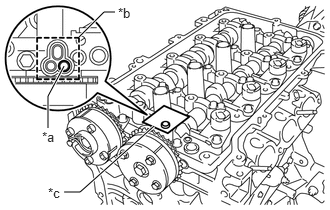
| *a | Prick a Hole |
| *b | Adhesive Tape Sealing Area |
| *c | Adhesive Tape |
After cleaning the VVT oil hole in the intake side of the No. 1 camshaft bearing cap, completely seal the oil hole with adhesive tape or equivalent as shown in the illustration to prevent air from leaking.
- NOTICE:
-
Be sure to cover the oil hole completely because air leaks due to insufficient sealing will prevent the lock pin from being released.
Prick a hole in the tape covering the oil hole as shown in the illustration. (Procedure A)
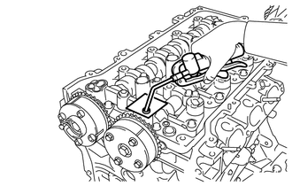
Apply approximately 150 kPa (1.5 kgf/cm2, 22 psi) of air pressure to the hole pricked in procedure A to release the lock pin.
- NOTICE:
- ·
If air leaks out, reattach the adhesive tape.
·Cover the oil hole with a piece of cloth when applying air pressure to prevent oil from spraying.
Forcibly turn the camshaft timing gear assembly in the advance direction (counterclockwise).
- HINT:
-
Depending on the air pressure applied, the camshaft timing gear assembly may turn in the advance direction without assistance.
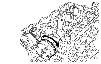
Turn the camshaft timing gear assembly within its movable range (26.5 to 28.5°) 2 or 3 times without turning it to the most retarded position. Make sure that the camshaft timing gear assembly turns smoothly.
Remove the adhesive tape from the No. 1 camshaft bearing cap.
13070A
3.INSPECT CAMSHAFT TIMING EXHAUST GEAR ASSEMBLY
Check the lock of the camshaft timing exhaust gear assembly.
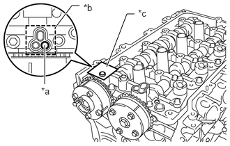
| *a | Prick a Hole |
| *b | Adhesive Tape Sealing Area |
| *c | Adhesive Tape |
After cleaning the VVT oil hole in the exhaust side of the No. 1 camshaft bearing cap, completely seal the oil hole with adhesive tape or equivalent as shown in the illustration to prevent air from leaking.
- NOTICE:
-
Be sure to cover the oil hole completely because air leaks due to insufficient sealing will prevent the lock pin from being released.
Prick a hole in the tape covering the oil hole as shown in the illustration. (Procedure A)
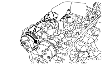
Apply approximately 200 kPa (2.0 kgf/cm2, 29 psi) of air pressure to the hole pricked in procedure A to release the lock pin.
- NOTICE:
- ·
If air leaks out, reattach the adhesive tape.
·Cover the oil hole with a piece of cloth when applying air pressure to prevent oil from spraying.
Using a screwdriver with its tip wrapped with protective tape, forcibly turn the camshaft timing exhaust gear assembly in the retard direction (clockwise).
- NOTICE:
- ·
Be sure to keep the camshaft timing exhaust gear assembly in the retard direction using a screwdriver. If the gear is released, it will return to the most advanced position automatically due to the force from the spring.
·Do not damage the camshaft timing exhaust gear assembly.
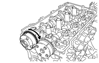
Using a screwdriver with its tip wrapped with protective tape, turn the camshaft timing exhaust gear assembly within its movable range (19 to 21°) 2 or 3 times without turning it to the most advanced position. Make sure that the camshaft timing exhaust gear assembly turns smoothly.
Remove the adhesive tape from the No. 1 camshaft bearing cap.
13050
4.REMOVE CAMSHAFT TIMING GEAR ASSEMBLY
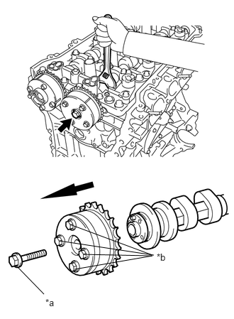
| *a | Bolt |
| *b | Do not remove |
Remove the bolt while holding the hexagonal portion of the camshaft, and then remove the camshaft timing gear assembly.
- NOTICE:
- ·
Before removing the camshaft timing gear assembly, make sure that the lock pin has been released.
·Be sure not to remove the other 4 bolts.
·Keep the camshaft timing gear assembly horizontal while removing it from the camshaft.
13070A
5.REMOVE CAMSHAFT TIMING EXHAUST GEAR ASSEMBLY
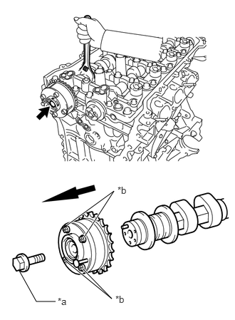
| *a | Bolt |
| *b | Do not remove |
Remove the bolt while holding the hexagonal portion of the No. 2 camshaft, and then remove the camshaft timing exhaust gear assembly.
- NOTICE:
- ·
Be sure not to remove the other 4 bolts.
·Keep the camshaft timing exhaust gear assembly horizontal while removing it from the No. 2 camshaft.
13908
6.REMOVE VALVE ROCKER ARM LOST MOTION DAMPER SUB-ASSEMBLY
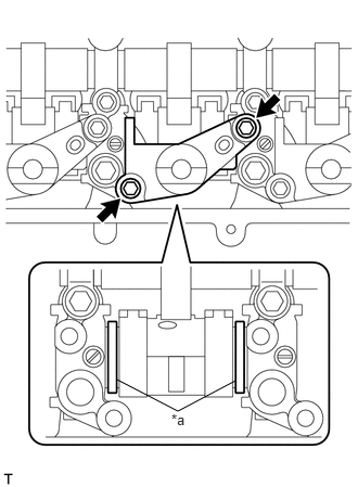
| *a | Shim |
Remove the 8 bolts and 4 valve rocker arm lost motion damper sub-assemblies.
- NOTICE:
- ·
Make sure the camshaft housing sub-assembly is installed to the cylinder head sub-assembly when removing or installing a valve rocker arm lost motion damper sub-assembly.
·If a valve rocker arm lost motion damper sub-assembly is removed, do not remove the camshaft housing sub-assembly.
·Do not remove the shims. If a shim is removed, replace the camshaft housing sub-assembly as engine malfunctions may result from irregular valve timing.
13908
7.INSTALL VALVE ROCKER ARM LOST MOTION DAMPER SUB-ASSEMBLY
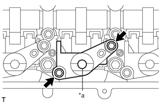
| *a | Hole for Engine Oil |
Install the 4 valve rocker arm lost motion damper sub-assemblies with the 8 bolts. Uniformly tighten the bolts.
- Torque:
- 10 N*m (102 kgf*cm, 7 ft.*lbf)
Add engine oil into the hole for engine oil.
11103
8.REMOVE CAMSHAFT HOUSING SUB-ASSEMBLY
- NOTICE:
- ·
The camshaft housing sub-assembly is replaced with an assembled unit that includes the camshaft housing, camshafts, camshaft bearing caps, valve rocker shaft, continuously variable valve lift controller assembly and valve rocker arm lost motion damper sub-assembly. If disassembled, replace the camshaft housing sub-assembly.
·The camshafts cannot be replaced by themselves.
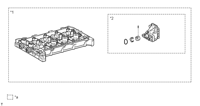 0.365,0.354 0.677,0.51 0.313,0.156 10 *1 3.938,0.573 4.25,0.729 0.313,0.156 10 *2 0.521,3.406 0.833,3.563 0.313,0.156 10 *a
*1 Camshaft Housing Sub-assembly *2 Continuously Variable Valve Lift Controller Assembly *a Set of parts that are replaced together - -
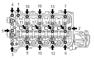
Uniformly loosen and remove the 17 bearing cap bolts in the order shown in the illustration.
- NOTICE:
-
Uniformly loosen the bearing cap bolts while keeping the camshaft housing level.
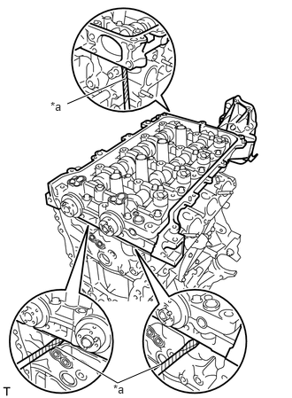
| *a | Protective Tape |
Using a screwdriver, remove the camshaft housing sub-assembly by prying between the cylinder head sub-assembly and camshaft housing sub-assembly.
- NOTICE:
-
Be careful not to damage the contact surfaces of the cylinder head sub-assembly and camshaft housing sub-assembly.
- HINT:
-
Tape the screwdriver tip before use.
13801
9.REMOVE NO. 1 VALVE ROCKER ARM SUB-ASSEMBLY
13750
10.REMOVE VALVE LASH ADJUSTER ASSEMBLY
13801
11.INSPECT NO. 1 VALVE ROCKER ARM SUB-ASSEMBLY
13750
12.INSPECT VALVE LASH ADJUSTER ASSEMBLY