AUDIO / VIDEO RADIO RECEIVER(for Radio and Display Type) REMOVAL
CAUTION / NOTICE / HINT
The necessary procedures (adjustment, calibration, initialization, or registration) that must be performed after parts are removed, installed, or replaced during the radio and display receiver assembly removal/installation are shown below.
| Replacement Part or Procedure | Necessary Procedures | Effects/Inoperative when not performed | Link |
|---|---|---|---|
| Disconnect cable from negative battery terminal | Memorize steering angle neutral point | Panoramic view monitor system | ( ) |
- NOTICE:
-
After the ignition switch is turned off, the radio and display receiver assembly records various types of memory and settings. As a result, after turning the ignition switch off, make sure to wait at least 120 seconds before disconnecting the cable from the negative (-) battery terminal.
- HINT:
- ·
When the cable is disconnected / reconnected to the battery terminal, systems temporarily stop operating. However, each system has a function that completes learning the first time the system is used.
-Learning completes when vehicle is driven
Effect/Inoperative Function When Necessary Procedures are not Performed Necessary Procedures Link *1: When performing learning using the GTS.
Click here(
)
Lane tracing assist system Drive the vehicle straight ahead at 35 km/h (22 mph) or more for 5 second or more. ( )
Pre-collision system Simple intelligent parking assist system*1 Parking support brake system*1
-Learning completes when vehicle is driven
Effect/Inoperative Function When Necessary Procedures are not Performed Necessary Procedures Link Power door lock control system
·Back door opener
Perform door unlock operation with door control switch or electrical key transmitter sub-assembly switch. ( )
Air conditioning system After the ignition switch is turned to ON, the servo motor standard position is recognized. -
·Use the same procedure for RHD and LHD vehicles.
·The following procedure is for LHD vehicles.
PROCEDURE

 1. PRECAUTION
- NOTICE:
- ·
After turning the ignition switch off, waiting time may be required before disconnecting the cable from the negative (-) battery terminal. Therefore, make sure to read the disconnecting the cable from the negative (-) battery terminal notices before proceeding with work.
Click hereGeneral>INTRODUCTION>REPAIR INSTRUCTION>PRECAUTION
·Precaution for audio and visual system:
2.DISCONNECT CABLE FROM NEGATIVE BATTERY TERMINAL
for 8NR-FTS:
for 3ZR-FAE:
55470
3.REMOVE INSTRUMENT CLUSTER FINISH PANEL GARNISH ASSEMBLY
55406B
4.REMOVE INSTRUMENT CLUSTER FINISH LOWER CENTER PANEL SUB-ASSEMBLY
55670A
5.REMOVE INSTRUMENT PANEL CENTER REGISTER ASSEMBLY
86140A
6.REMOVE RADIO AND DISPLAY RECEIVER ASSEMBLY WITH BRACKET
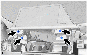
Remove the 4 screws.
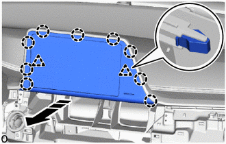

|
Remove in this Direction |
Pull the radio and display receiver assembly with bracket toward the rear of the vehicle to disengage the claws and clips as shown in the illustration.
Disconnect each connector and remove the radio and display receiver assembly with bracket.
55405B
7.REMOVE INSTRUMENT CLUSTER FINISH CENTER PANEL SUB-ASSEMBLY
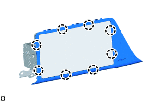
Disengage the claws to remove the instrument cluster finish center panel sub-assembly.
86211J
8.REMOVE NO. 1 RADIO RECEIVER BRACKET
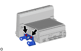
Remove the 2 screws and No. 1 radio receiver bracket from the radio and display receiver assembly.
86212C
9.REMOVE NO. 2 RADIO RECEIVER BRACKET
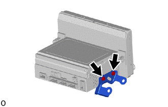
Remove the 2 screws and No. 2 radio receiver bracket from the radio and display receiver assembly.