 |
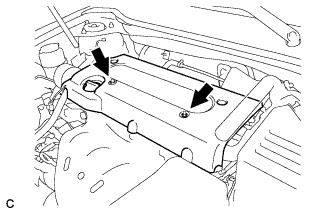
Remove the 2 nuts and cover.
CYLINDER HEAD > REMOVAL |
| 1. DISCHARGE FUEL SYSTEM PRESSURE |
| 2. DISCONNECT CABLE FROM NEGATIVE BATTERY TERMINAL |
| 3. REMOVE ENGINE UNDER COVER LH |
| 4. REMOVE ENGINE UNDER COVER RH |
| 5. REMOVE FRONT FENDER APRON SEAL RH |
| 6. REMOVE NO. 1 ENGINE COVER SUB-ASSEMBLY |
|
Remove the 2 nuts and cover.
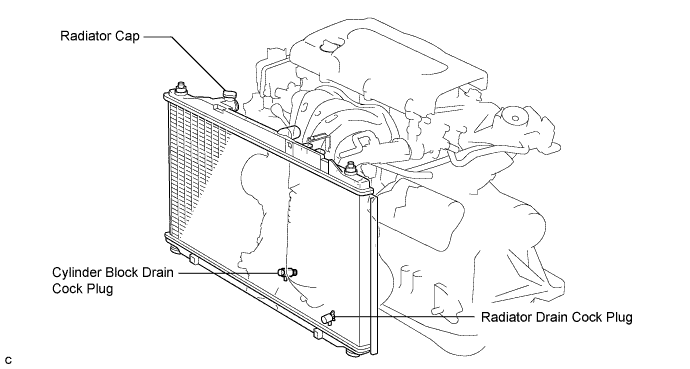
| 7. DRAIN ENGINE COOLANT |
Remove the radiator cap sub-assembly from the radiator assembly.
Loosen the radiator drain cock plug and cylinder block drain cock plug, then drain the coolant.
| 8. DRAIN ENGINE OIL |
Remove the oil filler cap.
Remove the oil drain plug and drain the oil into a container.
| 9. REMOVE WINDSHIELD WIPER LINK ASSEMBLY |
| 10. REMOVE COWL TOP PANEL OUTER SUB-ASSEMBLY |
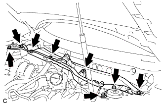 |
Remove the 4 bolts, 4 nuts and outer cowl top panel sub-assembly.
| 11. REMOVE AIR CLEANER INLET ASSEMBLY |
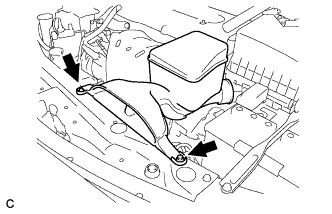 |
Remove the 2 bolts, clamp and air cleaner inlet.
| 12. REMOVE AIR CLEANER CAP SUB-ASSEMBLY |
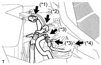 |
Disconnect the mass air flow meter connector (*1).
Disconnect the purge VSV connector (*2).
Disconnect the 2 purge VSV vacuum hoses (*3).
Disconnect the purge line hose from the clamp (*4).
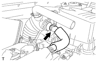 |
Disconnect the No. 2 ventilation hose from the air cleaner hose.
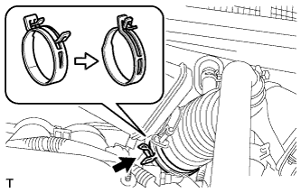 |
Lock the No. 1 air cleaner hose clamp, and then disconnect the No. 1 air cleaner hose from the throttle body.
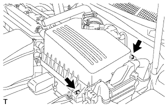 |
Remove the 2 bolts and air cleaner cap.
Remove the air cleaner filter element from the air cleaner case.
| 13. REMOVE AIR CLEANER CASE SUB-ASSEMBLY |
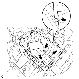 |
Disconnect the hose clamp.
Remove the 3 bolts and air cleaner case.
| 14. REMOVE BATTERY |
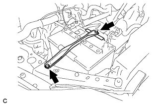 |
Loosen the bolt and nut, and remove the battery clamp.
Remove the battery and battery tray.
| 15. REMOVE THROTTLE BODY ASSEMBLY |
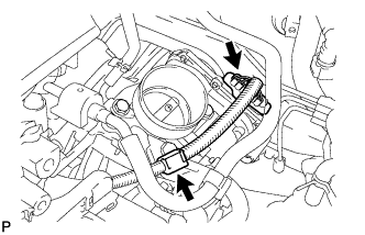 |
Disconnect the throttle position sensor connector and wire harness clamp.
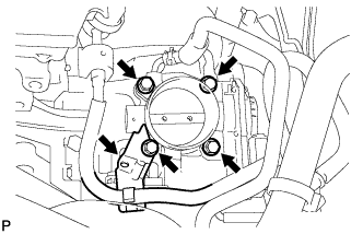 |
Remove the 4 bolts, and then remove the fuel pipe support and throttle body.
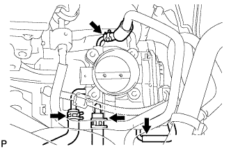 |
Disconnect the purge line hose from the throttle body.
Disconnect the water by-pass hose from the throttle body.
Disconnect the No. 2 water by-pass hose from the throttle body.
Disconnect the No. 1 throttle body hose from the throttle body.
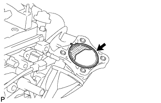 |
Remove the gasket from the intake manifold.
| 16. DISCONNECT FUEL TUBE SUB-ASSEMBLY |
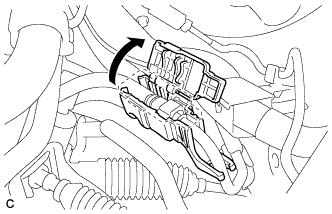 |
Remove the No. 1 fuel pipe clamp.
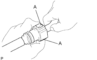 |
Disconnect the connector from the tube while pinching part A with your fingers as shown in the illustration.
| 17. REMOVE FUEL DELIVERY PIPE WITH INJECTOR |
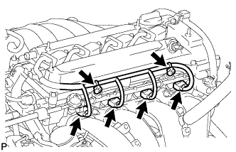 |
Remove the 2 wire harness clamps.
Disconnect the 4 fuel injector connectors.
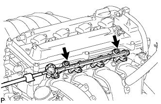 |
Remove the 2 bolts, then remove the fuel delivery pipe together with the 4 fuel injectors.
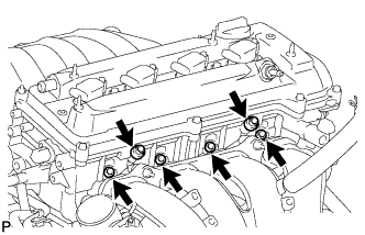 |
Remove the 2 delivery pipe spacers from the cylinder head.
Remove the 4 insulators from the cylinder head.
| 18. REMOVE INTAKE MANIFOLD |
Disconnect the union to check valve hose from the brake booster.
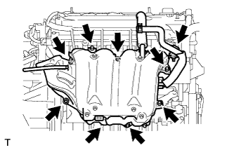 |
Disconnect the camshaft timing oil control valve connector.
Remove the wire harness clamp.
Remove the union to check valve hose from the vacuum hose clamp.
Remove the 5 bolts, 2 nuts and intake manifold.
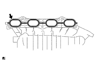 |
Remove the gasket from the intake manifold.
| 19. REMOVE NO. 1 INTAKE MANIFOLD INSULATOR |
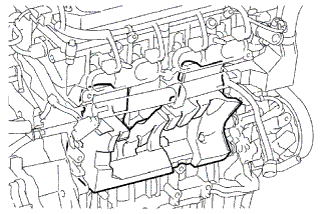 |
Remove the intake manifold insulator from the cylinder block.
| 20. REMOVE FRONT EXHAUST PIPE ASSEMBLY |
| 21. REMOVE NO. 2 ENGINE MOUNTING STAY RH |
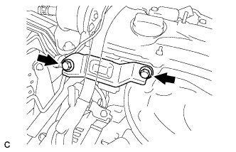 |
Remove the 2 bolts and No. 2 mounting stay RH.
| 22. REMOVE ENGINE MOVING CONTROL ROD SUB-ASSEMBLY |
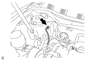 |
Remove the bolt and disconnect the ground cable.
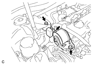 |
Remove the 3 bolts and the engine moving control rod with bracket.
| 23. REMOVE NO. 2 ENGINE MOUNTING BRACKET RH |
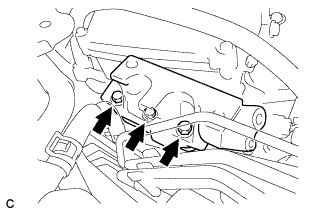 |
Remove the 3 bolts and No. 2 mounting bracket RH.
| 24. REMOVE V-RIBBED BELT |
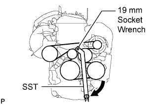 |
Using SST and 19 mm socket wrench, loosen the V-ribbed belt tensioner arm clockwise, then remove the V-ribbed belt.
| 25. REMOVE GENERATOR ASSEMBLY |
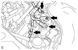 |
Disconnect the generator connector.
Remove the nut and disconnect the wire harness from terminal B.
Remove the bolt and wire harness clamp bracket.
Remove the wire harness clamps.
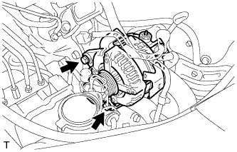 |
Remove the 2 bolts and generator assembly.
| 26. REMOVE OIL LEVEL GAUGE SUB-ASSEMBLY |
| 27. REMOVE OIL LEVEL GAUGE GUIDE |
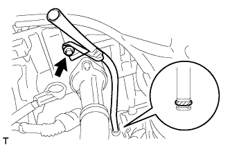 |
Remove the bolt and oil level gauge guide.
Remove the O-ring from the oil level gauge guide.
| 28. REMOVE MANIFOLD STAY |
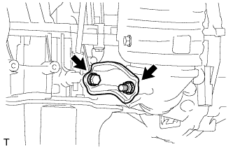 |
Remove the bolt, nut and stay.
| 29. REMOVE NO. 2 MANIFOLD STAY |
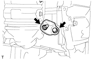 |
Remove the bolt, nut and stay.
| 30. REMOVE EXHAUST MANIFOLD CONVERTER SUB-ASSEMBLY |
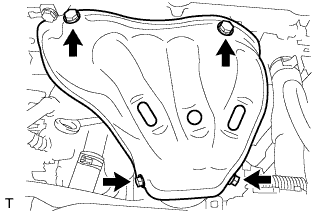 |
Remove the 4 bolts and No. 1 insulator.
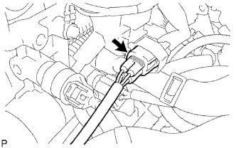 |
Disconnect the air-fuel ratio sensor connector.
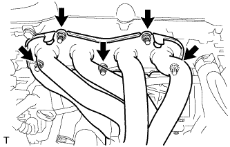 |
Remove the 5 nuts, manifold converter and gasket.
| 31. REMOVE CHAIN SUB-ASSEMBLY |
| 32. REMOVE NO. 2 CAMSHAFT |
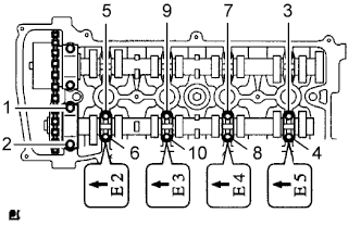 |
Using several steps, uniformly loosen and remove the 10 bearing cap bolts in the sequence shown in the illustration.
Remove the 5 bearing caps and No. 2 camshaft.
| 33. REMOVE CAMSHAFT |
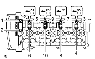 |
Using several steps, uniformly loosen and remove the 10 bearing cap bolts in the sequence shown in the illustration.
Remove the 5 bearing caps and camshaft.
| 34. REMOVE CAMSHAFT TIMING OIL CONTROL VALVE ASSEMBLY |
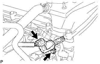 |
Disconnect the camshaft timing oil control valve assembly connector.
Remove the bolt and camshaft timing oil control valve assembly.
| 35. DISCONNECT RADIATOR HOSE INLET |
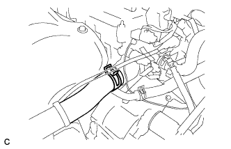 |
Remove the clamp and disconnect the radiator hose inlet.
| 36. DISCONNECT ENGINE WIRE |
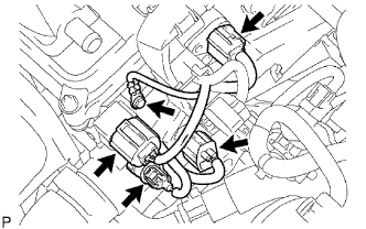 |
Disconnect the radio setting condenser connector.
Disconnect the engine oil pressure switch connector.
Disconnect the engine coolant temperature sensor connector.
Disconnect the camshaft position sensor connector.
Remove the bolt and ground cable.
| 37. REMOVE NO. 2 CAMSHAFT BEARING |
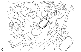 |
Remove the No. 2 camshaft bearing.
| 38. REMOVE CYLINDER HEAD SUB-ASSEMBLY |
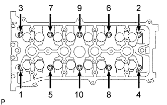 |
Using several steps, uniformly loosen and remove the 10 cylinder head bolts and 10 plate washers with a 10 mm bi-hexagon wrench in the sequence shown in the illustration.
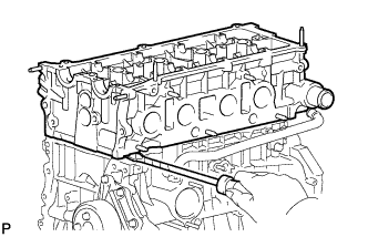 |
Using a screwdriver with its tip wrapped with tape, pry between the cylinder head and cylinder block, and remove the cylinder head.
| 39. REMOVE CYLINDER HEAD GASKET |
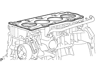 |
Remove the cylinder head gasket.