STEERING COLUMN STEERING COLUMN ASSEMBLY REMOVAL
PROCEDURE

 1. PRECAUTION
2.TURN FRONT WHEELS TO FACE STRAIGHT AHEAD
3.REMOVE FRONT WHEEL
45130
4.REMOVE HORN BUTTON ASSEMBLY
45100
5.REMOVE STEERING WHEEL ASSEMBLY
67914B
6.REMOVE FRONT DOOR SCUFF PLATE LH (for LHD)
62112A
7.REMOVE COWL SIDE TRIM SUB-ASSEMBLY LH (for LHD)
62312B
8.DISCONNECT FRONT DOOR OPENING TRIM WEATHERSTRIP LH (for LHD)
55318C
9.REMOVE INSTRUMENT SIDE PANEL LH (for LHD)
53601
10.DISCONNECT HOOD LOCK CONTROL LEVER SUB-ASSEMBLY (for LHD)
55432D
11.REMOVE LOWER NO. 1 INSTRUMENT PANEL FINISH PANEL ASSEMBLY (for LHD)
73900
12.REMOVE LOWER NO. 1 INSTRUMENT PANEL AIRBAG ASSEMBLY (for RHD)
45287
13.REMOVE LOWER STEERING COLUMN COVER
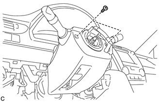
Remove the 2 screws.
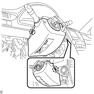
Push the right and left sides of the lower steering column cover, and disengage the 2 claws.
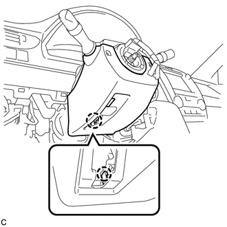
Insert a finger into the opening of the tilt lever of the lower steering column cover to disengage the claw and remove the lower steering column cover.
45286B
14.REMOVE UPPER STEERING COLUMN COVER
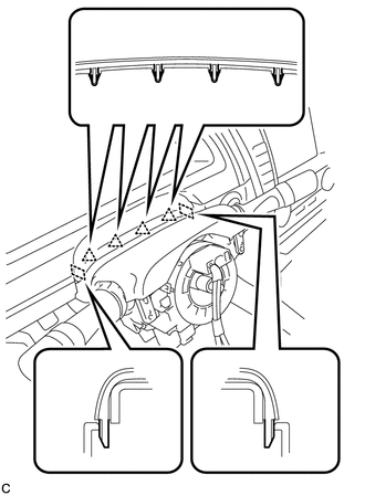
Disengage the 4 clips and 2 guides from the upper steering column cover.
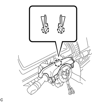
Disengage the 2 claws to remove the upper steering column cover.
15.REMOVE TURN SIGNAL SWITCH ASSEMBLY WITH SPIRAL CABLE SUB-ASSEMBLY
- NOTICE:
- w/o VSC
- ·
Do not replace the spiral cable sub-assembly with the battery connected and the ignition switch to ON.
·Do not rotate the spiral cable sub-assembly without the steering wheel with the battery connected and the ignition switch to ON.
- NOTICE:
- w/ VSC
- ·
Do not replace the spiral cable with sensor sub-assembly with the battery connected and the ignition switch to ON.
·Do not rotate the spiral cable with sensor sub-assembly without the steering wheel with the battery connected and the ignition switch to ON.
·Ensure that the steering wheel is installed and aligned straight when inspecting the steering sensor.
Disconnect the connectors from the turn signal switch assembly with spiral cable sub-assembly.
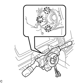
Disengage the 3 claws to remove the turn signal switch assembly with spiral cable sub-assembly from the steering post assembly.
45220
16.SEPARATE STEERING INTERMEDIATE SHAFT ASSEMBLY
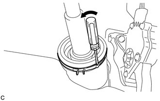
Using a screwdriver, loosen the clamp as shown in the illustration.
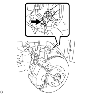
| *a | Matchmark |
Put matchmarks on the steering intermediate shaft assembly and the steering link assembly.
Remove the bolt and separate the steering intermediate shaft assembly from the steering link assembly.
87201B
17.REMOVE NO. 2 AIR DUCT SUB-ASSEMBLY (for LHD)
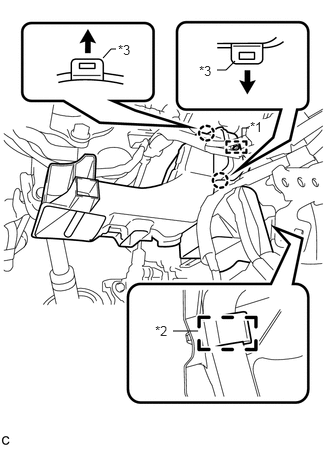
| *1 | Guide |
| *2 | Clamp |
| *3 | Claw |
Using a screwdriver, Disengage the 2 claws and guide.
- NOTICE:
-
Do not lift the claw excessively.
- HINT:
-
When disengaging the claw, insert a screwdriver under the end of the claw and lift it gently.
Disengage the clamp to remove the No. 2 air duct sub-assembly.
87201B
18.REMOVE NO. 2 AIR DUCT SUB-ASSEMBLY (for RHD)
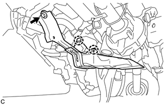
Remove the bolt.
Disengage the 2 claws to remove the No. 2 air duct sub-assembly.
19.REMOVE STEERING POST ASSEMBLY
Disconnect the connectors and disengage the wire harness clamps from the steering post assembly.
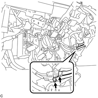
Disconnect the 2 connectors.
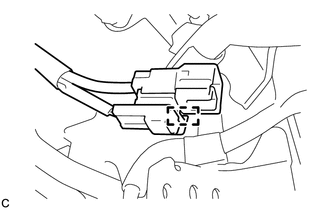
Disengage the clamp.
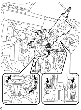
Remove the bolt to separate the ground wire.
Remove the 4 nuts and the steering post assembly.
45220
20.REMOVE STEERING INTERMEDIATE SHAFT ASSEMBLY
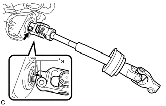
| *a | Matchmark |
Remove the bolt and slide the steering intermediate shaft assembly.
- NOTICE:
-
Do not remove the steering intermediate shaft assembly from the steering column assembly.
Put matchmarks on the steering intermediate shaft assembly and the steering column assembly.
Remove the steering intermediate shaft assembly from the steering column assembly.