INTERIOR PANELS / TRIM INSTRUMENT PANEL SAFETY PAD REMOVAL
PROCEDURE

 1. PRECAUTION
Click hereVehicle Interior>INTERIOR PANELS / TRIM>INSTRUMENT PANEL SAFETY PAD>PRECAUTION
- NOTICE:
-
After turning the ignition switch off, waiting time may be required before disconnecting the cable from the negative (-) battery terminal. Therefore, make sure to read the disconnecting the cable from the negative (-) battery terminal notices before proceeding with work.
-
Click hereGeneral>INTRODUCTION>REPAIR INSTRUCTION>PRECAUTION
2.DISCONNECT CABLE FROM NEGATIVE BATTERY TERMINAL
- CAUTION:
-
Wait at least 90 seconds after disconnecting the cable from the negative (-) battery terminal to disable the SRS system.
- NOTICE:
-
When disconnecting the cable, some systems need to be initialized after the cable is reconnected.
-
Click hereGeneral>INTRODUCTION>REPAIR INSTRUCTION>INITIALIZATION
67914
3.REMOVE FRONT DOOR SCUFF PLATE LH
62112A
4.REMOVE COWL SIDE TRIM SUB-ASSEMBLY LH
62312B
5.DISCONNECT FRONT DOOR OPENING TRIM WEATHERSTRIP LH
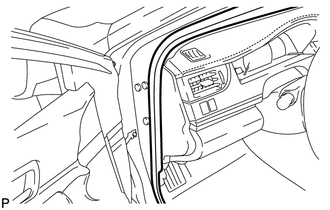
Disconnect the front door opening trim weatherstrip LH.
55318C
6.REMOVE INSTRUMENT SIDE PANEL LH
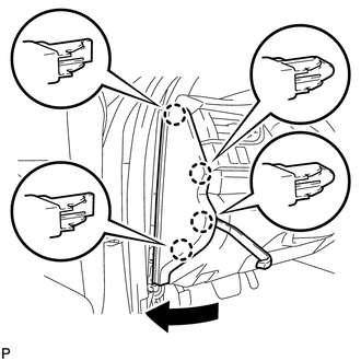
Using a moulding remover, disengage the 4 claws as shown in the illustration.
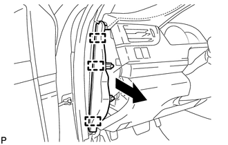
Disengage the 3 guides and remove the instrument side panel LH as shown in the illustration.
55474C
7.REMOVE NO. 1 INSTRUMENT CLUSTER FINISH PANEL GARNISH (for LHD)
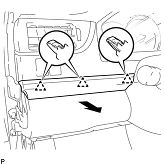
Disengage the 3 clips to remove the No. 1 instrument cluster finish panel garnish as shown in the illustration.
55431B
8.REMOVE UPPER INSTRUMENT PANEL FINISH PANEL (for RHD)
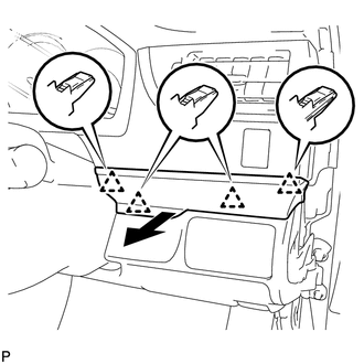
Disengage the 4 clips to remove the upper instrument panel finish panel as shown in the illustration.
w/ Smart Entry and Start System
Disconnect the connector.
55650
9.REMOVE NO. 1 INSTRUMENT PANEL REGISTER ASSEMBLY
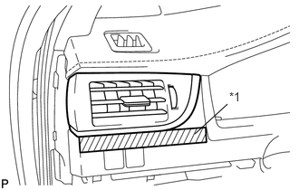
| *1 | Protective Tape |
Apply protective tape to the area shown in the illustration.
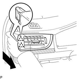
Disengage the 2 clips as shown in the illustration.
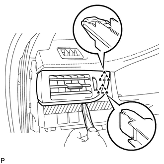
Using a moulding remover, disengage the 2 clips to remove the No. 1 instrument panel register assembly.
55410C
10.REMOVE INSTRUMENT CLUSTER FINISH PANEL ASSEMBLY
Operate the tilt and telescopic lever to fully extend and lower the steering column assembly.
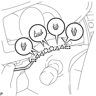
Using a moulding remover, disengage the 2 claws, 4 clips and 2 guides.
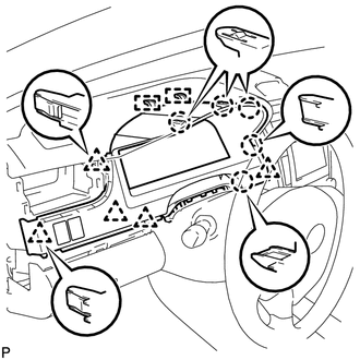
Disengage the 5 claws, 5 clips and 2 guides.
Disconnect each connector.
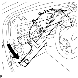
Remove the instrument cluster finish panel assembly as shown in the illustration.
83100
11.REMOVE COMBINATION METER ASSEMBLY
53922B
12.REMOVE FRONT PANEL GARNISH LH
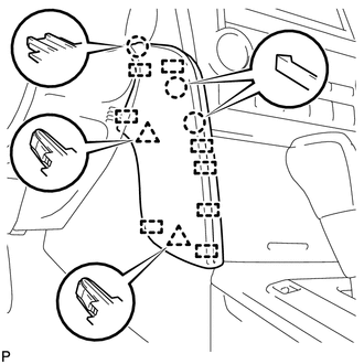
Disengage the 3 claws, 2 clips and 8 guides to remove the front panel garnish LH.
53601
13.DISCONNECT HOOD LOCK CONTROL LEVER SUB-ASSEMBLY
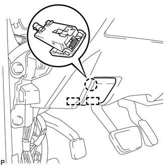
Disengage the claw and 2 guides to disconnect the hood lock control lever sub-assembly.
14.REMOVE LOWER NO. 1 INSTRUMENT PANEL FINISH PANEL ASSEMBLY (for LHD)
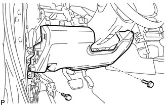
Remove the 2 bolts <B>.
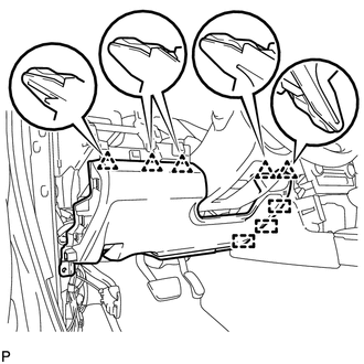
Disengage the 5 clips and 3 guides to remove the lower No. 1 instrument panel finish panel assembly.
15.REMOVE LOWER NO. 1 INSTRUMENT PANEL FINISH PANEL ASSEMBLY (for RHD)
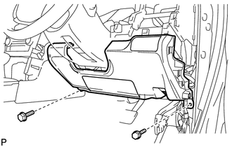
Remove the 2 bolts <B>.
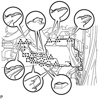
Disengage the 4 claws, 9 clips and 3 guides to remove the lower No. 1 instrument panel finish panel assembly.
53921B
16.REMOVE FRONT PANEL GARNISH RH
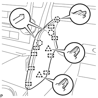
Disengage the 3 claws, 2 clips and 8 guides to remove the front panel garnish RH.
33504F
17.REMOVE SHIFT LEVER KNOB SUB-ASSEMBLY (for Automatic Transaxle)
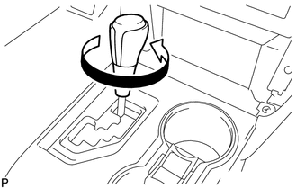
Turn the shift lever knob sub-assembly counterclockwise and remove the shift lever knob sub-assembly.
58805C
18.REMOVE REAR CONSOLE UPPER PANEL SUB-ASSEMBLY (for Automatic Transaxle)
Move the shift lever to N.
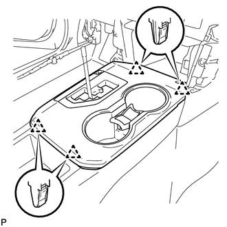
Disengage the 4 clips.
Disconnect each connector and remove the rear console upper panel sub-assembly.
58801E
19.REMOVE UPPER CONSOLE BOX SUB-ASSEMBLY (for Automatic Transaxle)
58864B
20.REMOVE NO. 4 CONSOLE BOX DUCT (for Automatic Transaxle)
58815A
21.REMOVE CONSOLE BOX CARPET (for Automatic Transaxle)
22.REMOVE REAR CONSOLE BOX ASSEMBLY (for Automatic Transaxle)
33504F
23.REMOVE SHIFT LEVER KNOB SUB-ASSEMBLY (for Manual Transaxle)
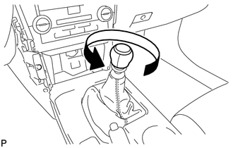
Turn the shift lever knob sub-assembly counterclockwise and remove the shift lever knob sub-assembly.
58904B
24.REMOVE PARKING BRAKE HOLE COVER SUB-ASSEMBLY (for Manual Transaxle)
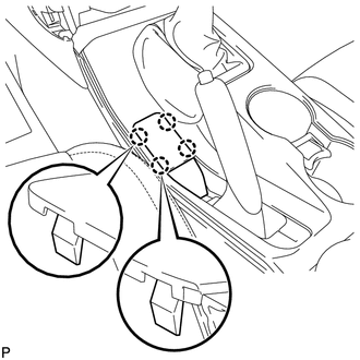
Disengage the 4 claws and remove the parking brake hole cover sub-assembly.
58805C
25.REMOVE REAR CONSOLE UPPER PANEL SUB-ASSEMBLY (for Manual Transaxle)
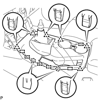
Disengage the 6 clips, 2 claws and 6 guides and remove the rear console upper panel sub-assembly.
58815A
26.REMOVE CONSOLE BOX CARPET (for Manual Transaxle)
27.REMOVE REAR CONSOLE BOX ASSEMBLY (for Manual Transaxle)
28.REMOVE CENTER INSTRUMENT CLUSTER FINISH PANEL ASSEMBLY
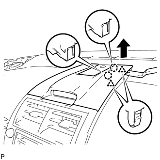
Using a moulding remover, disengage the 2 claws and 2 clips as shown in the illustration.
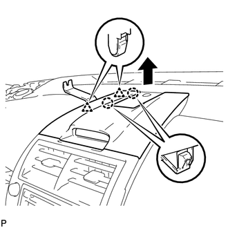
Using a moulding remover, disengage the 2 claws and 2 clips as shown in the illustration.
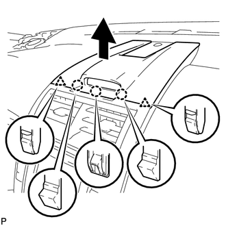
Disengage the 3 claws and 2 clips as shown in the illustration.
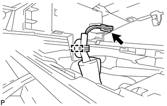
Disengage the clamp.
Disconnect the connector to remove the center instrument cluster finish panel assembly.
55660
29.REMOVE NO. 2 INSTRUMENT PANEL REGISTER ASSEMBLY
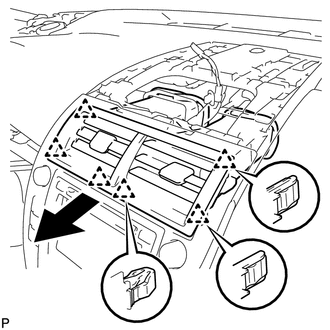
Pull the No. 2 instrument panel register assembly in the direction indicated by the arrow to disengage the 6 clips to remove the No. 2 instrument panel register assembly.
58916
30.REMOVE BOX BOTTOM MAT
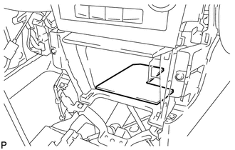
Remove the box bottom mat.
58804A
31.REMOVE UPPER CONSOLE PANEL SUB-ASSEMBLY
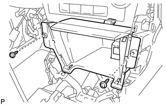
Remove the 2 screws <C> or <D>.
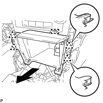
Disengage the 4 clips and guide as shown in the illustration.
Disconnect each connector to remove the upper console panel sub-assembly.
32.REMOVE CENTER INSTRUMENT CLUSTER FINISH PANEL WITH AIR CONDITIONING CONTROL ASSEMBLY (w/o Radio Receiver)
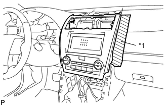
| *1 | Protective Tape |
Apply protective tape to the areas shown in the illustration.
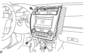
Remove the 4 bolts.
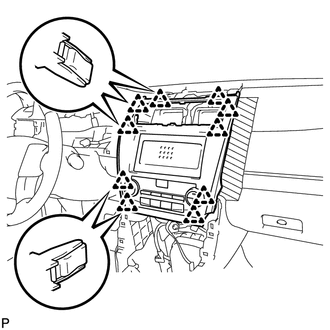
Pull the center instrument cluster finish panel with air conditioning control assembly toward the rear of the vehicle and disengage the 10 clips.
Disconnect the connector and remove the center instrument cluster finish panel with air conditioning control assembly.
33.REMOVE RADIO RECEIVER ASSEMBLY WITH AIR CONDITIONING CONTROL ASSEMBLY (w/o Navigation System)
34.REMOVE NAVIGATION RECEIVER ASSEMBLY WITH AIR CONDITIONING CONTROL ASSEMBLY (w/ Navigation System)
55510F
35.REMOVE NO. 1 SPEAKER OPENING COVER ASSEMBLY
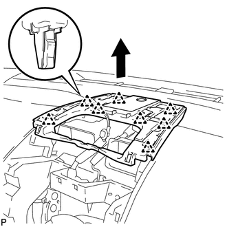
Disengage the 8 clips as shown in the illustration.
Disconnect the connector to remove the No. 1 speaker opening cover assembly.
86160J
36.REMOVE FRONT NO. 3 SPEAKER ASSEMBLY (for 10 Speakers)
67911B
37.REMOVE FRONT DOOR SCUFF PLATE RH
- HINT:
-
Use the same procedure as for the LH side.
-
Click hereVehicle Interior>INTERIOR PANELS / TRIM>ROOF HEADLINING>REMOVAL
62111A
38.REMOVE COWL SIDE TRIM SUB-ASSEMBLY RH
- HINT:
-
Use the same procedure as for the LH side.
-
Click hereVehicle Interior>INTERIOR PANELS / TRIM>ROOF HEADLINING>REMOVAL
62311B
39.DISCONNECT FRONT DOOR OPENING TRIM WEATHERSTRIP RH
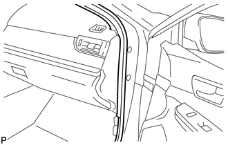
Disconnect the front door opening trim weatherstrip RH.
55317A
40.REMOVE INSTRUMENT SIDE PANEL RH
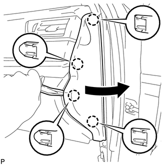
Using a moulding remover, disengage the 4 claws as shown in the illustration.
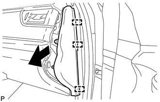
Disengage the 3 guides to remove the instrument side panel RH as shown in the illustration.
55607
41.REMOVE NO. 2 INSTRUMENT PANEL UNDER COVER SUB-ASSEMBLY
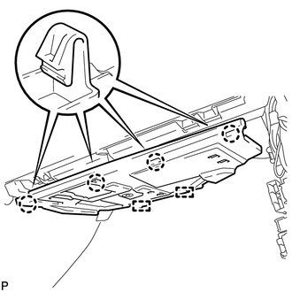
Disengage the 4 claws.
Disengage the 2 guides.
Disconnect the connector and remove the No. 2 instrument panel under cover sub-assembly.
55303B
42.REMOVE LOWER INSTRUMENT PANEL SUB-ASSEMBLY
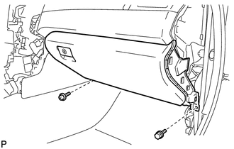
Remove the bolt <B> and screw <C> or <D>.
Open the lower instrument panel door.
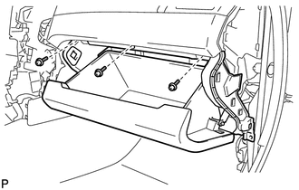
Remove the 3 screws <C> or <D>.
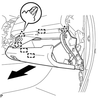
Disengage the 2 clips, 4 guides and remove the lower instrument panel sub-assembly as shown in the illustration.
55475A
43.REMOVE NO. 2 INSTRUMENT CLUSTER FINISH PANEL GARNISH
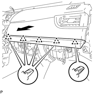
Disengage the 5 clips to remove the No. 2 instrument cluster finish panel garnish as shown in the illustration.
55670
44.REMOVE NO. 3 INSTRUMENT PANEL REGISTER ASSEMBLY
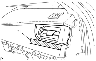
| *1 | Protective Tape |
Apply protective tape to the area shown in the illustration.
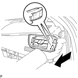
Disengage the 2 clips as shown in the illustration.
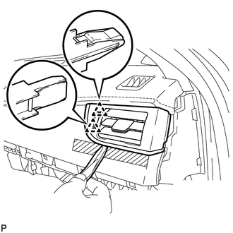
Using a moulding remover, disengage the 2 clips to remove the No. 3 instrument panel register assembly.
62212
45.REMOVE FRONT PILLAR GARNISH LH (w/o Curtain Shield Airbag)
62212
46.REMOVE FRONT PILLAR GARNISH LH (w/ Curtain Shield Airbag)
55408F
47.REMOVE NO. 1 INSTRUMENT PANEL SPEAKER PANEL SUB-ASSEMBLY
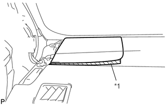
| *1 | Protective Tape |
Apply protective tape to the area shown in the illustration.
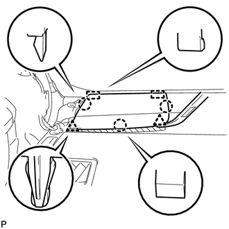
Using a moulding remover, disengage the 2 clips and 3 claws.
Disengage the 2 guides to remove the No.1 instrument panel speaker panel sub-assembly.
86160P
48.REMOVE FRONT NO. 2 SPEAKER ASSEMBLY (for LH Side)
62211
49.REMOVE FRONT PILLAR GARNISH RH (w/o Curtain Shield Airbag)
- HINT:
-
Use the same procedure as for the LH side.
-
Click hereVehicle Interior>INTERIOR PANELS / TRIM>ROOF HEADLINING>REMOVAL
62211
50.REMOVE FRONT PILLAR GARNISH RH (w/ Curtain Shield Airbag)
- HINT:
-
Use the same procedure as for the LH side.
-
Click hereVehicle Interior>INTERIOR PANELS / TRIM>ROOF HEADLINING>REMOVAL
55409F
51.REMOVE NO. 2 INSTRUMENT PANEL SPEAKER PANEL SUB-ASSEMBLY
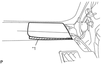
| *1 | Protective Tape |
Apply protective tape to the area shown in the illustration.
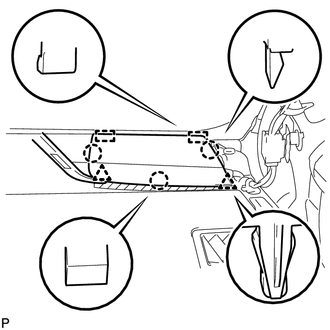
Using a moulding remover, disengage the 2 clips and 3 claws.
Disengage the 2 guides to remove the No. 2 instrument panel speaker panel sub-assembly.
86160P
52.REMOVE FRONT NO. 2 SPEAKER ASSEMBLY (for RH Side)
- HINT:
-
Use the same procedure as for the LH side.
-
Click hereAudio / Visual / Telematics>AUDIO / VIDEO>INSTRUMENT PANEL SPEAKER>REMOVAL
55480D
53.REMOVE LOWER INSTRUMENT PANEL FINISH PANEL ASSEMBLY
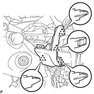
Disengage the 4 clips to remove the lower instrument panel finish panel assembly.
for LHD with Smart Entry and Start System:
Disconnect the connector.
58817A
54.REMOVE FRONT NO. 2 CONSOLE BOX INSERT
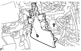
Remove the 2 screws <C> or <D>.
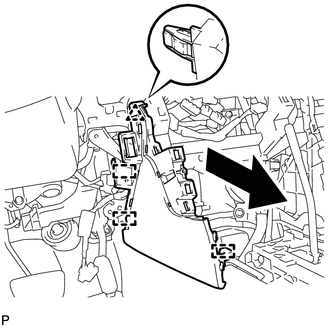
Disengage the clip and 3 guides and remove the front No. 2 console box insert as shown in the illustration.
for LHD with Automatic Air Conditioning System:
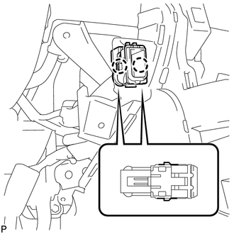
Disengage the 2 claws to disconnect the room temperature sensor from the front No. 2 console box insert.
58816B
55.REMOVE CONSOLE BOX INSERT
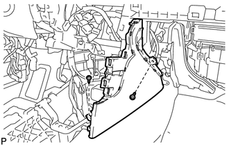
Remove the 2 screws <C> or <D>.
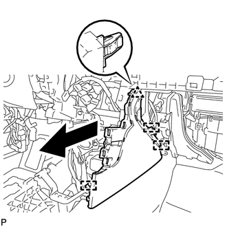
Disengage the clip and 3 guides and remove the console box insert as shown in the illustration.
for RHD with Automatic Air Conditioning System:
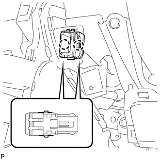
Disengage the 2 claws to disconnect the room temperature sensor from the console box insert.
55011A
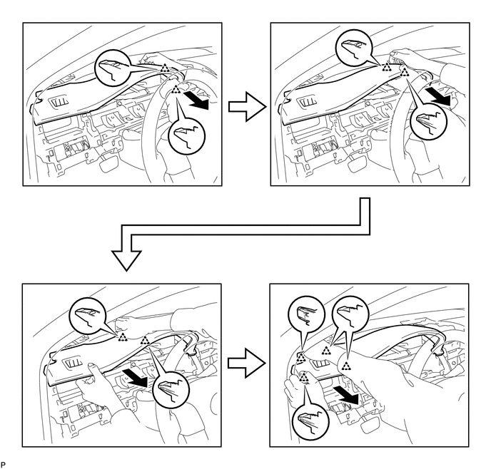
56.REMOVE NO. 1 INSTRUMENT PANEL GARNISH SUB-ASSEMBLY
Disengage the 10 clips to remove the No.1 instrument panel garnish sub-assembly as shown in the illustration.
82142A
57.DISCONNECT NO. 2 INSTRUMENT PANEL WIRE
58.REMOVE INSTRUMENT PANEL SAFETY PAD ASSEMBLY
Disconnect each connector.
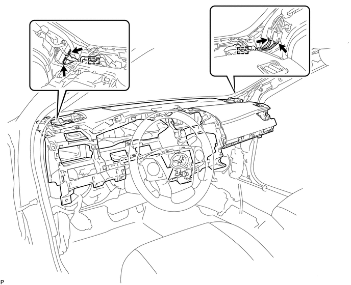
Disengage each clamp.
Remove the 2 passenger airbag bolts <A>.
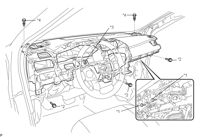
| *1 | Passenger Airbag Bolt <A> | *2 | Bolt <B> |
| *3 | Nut <F> or <G> | *4 | Clip |
Remove the 3 bolts <B> and nut <F> or <G>.
Remove the 2 clips.
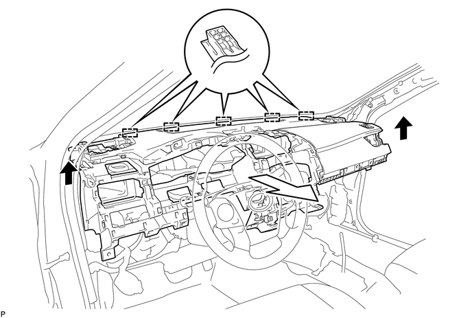
Disengage the 5 guides and remove the instrument panel safety pad assembly as shown in the illustration.
- NOTICE:
- ·
Do not damage the instrument panel safety pad assembly.
·Do not allow the wire harnesses to interfere with the surrounding parts.