U760E AUTOMATIC TRANSMISSION / TRANSAXLE SHIFT LEVER INSTALLATION
PROCEDURE

 33525
1.INSTALL SHIFT LEVER SUPPORT
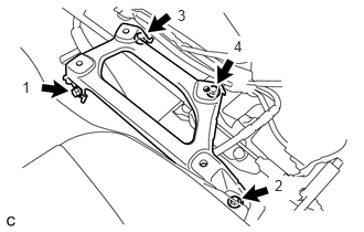
Install the shift lever support with the 4 bolts in the sequence shown in the illustration.
- Torque:
- 12 N*m (122 kgf*cm, 9 ft.*lbf)
33560C
2.INSTALL LOWER SHIFT LEVER ASSEMBLY
- NOTICE:
-
Check that the park/neutral position switch and the shift lever are in neutral.
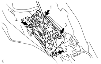
Install the lower shift lever assembly with the 4 bolts in the sequence shown in the illustration.
- Torque:
- 12 N*m (122 kgf*cm, 9 ft.*lbf)
Connect the 2 clamps and 2 connectors.
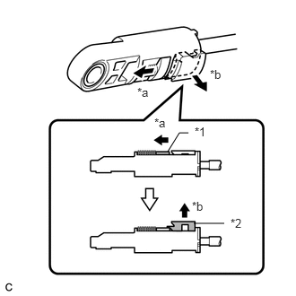
| *1 | Slider |
| *2 | Lock Piece |
| *a | Slide |
| *b | Pull |
Slide the slider of the transmission control cable in the direction indicated by the arrow and pull the lock piece outward.
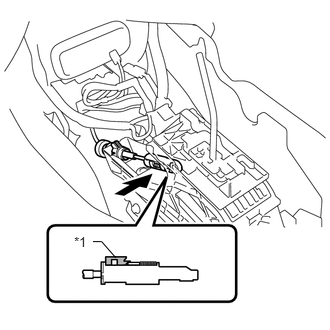
| *1 | Lock Piece |
Install the transmission control cable end to the lower shift lever assembly.
- NOTICE:
- ·
Check that the lock piece is pulled up.
·Install the cable end all the way to the base of the pin.
Push the lock piece into the adjuster case.
- NOTICE:
- ·
Check that the park/neutral position switch and the shift lever are in neutral.
·Securely push in the lock piece until the slider lock is engaged.
58861B
3.INSTALL NO. 1 CONSOLE BOX DUCT
Install the clip and No. 1 console box duct.
58995A
4.INSTALL NO. 1 CONSOLE BOX MOUNTING BRACKET
Install the No. 1 console box mounting bracket to the lower shift lever assembly with the screw.
58544A
5.INSTALL FLOOR CARPET BRACKET LH
58816B
6.INSTALL CONSOLE BOX INSERT
58817A
7.INSTALL FRONT NO. 2 CONSOLE BOX INSERT
58804A
8.INSTALL UPPER CONSOLE PANEL SUB-ASSEMBLY
58916
9.INSTALL BOX BOTTOM MAT
55303B
10.INSTALL LOWER INSTRUMENT PANEL SUB-ASSEMBLY
55607
11.INSTALL NO. 2 INSTRUMENT PANEL UNDER COVER SUB-ASSEMBLY
55317A
12.INSTALL INSTRUMENT SIDE PANEL RH
62311B
13.INSTALL FRONT DOOR OPENING TRIM WEATHERSTRIP RH
62111A
14.INSTALL COWL SIDE TRIM SUB-ASSEMBLY RH
67913
15.INSTALL FRONT DOOR SCUFF PLATE RH
16.INSTALL LOWER NO. 1 INSTRUMENT PANEL FINISH PANEL ASSEMBLY (for LHD)
17.INSTALL LOWER NO. 1 INSTRUMENT PANEL FINISH PANEL ASSEMBLY (for RHD)
53601
18.CONNECT HOOD LOCK CONTROL LEVER SUB-ASSEMBLY
55318C
19.INSTALL INSTRUMENT SIDE PANEL LH
62312B
20.INSTALL FRONT DOOR OPENING TRIM WEATHERSTRIP LH
62112A
21.INSTALL COWL SIDE TRIM SUB-ASSEMBLY LH
67914
22.INSTALL FRONT DOOR SCUFF PLATE LH
23.INSTALL REAR CONSOLE BOX ASSEMBLY
24.INSPECT SHIFT LEVER POSITION