| B |  |
| GO TO DTC CHART (Click here) |
DTC P0300 Random / Multiple Cylinder Misfire Detected |
DTC P0301 Cylinder 1 Misfire Detected |
DTC P0302 Cylinder 2 Misfire Detected |
DTC P0303 Cylinder 3 Misfire Detected |
DTC P0304 Cylinder 4 Misfire Detected |
DTC P0305 Cylinder 5 Misfire Detected |
DTC P0306 Cylinder 6 Misfire Detected |
| DTC No. | DTC Detection Condition | Trouble Area |
| P0300 | Simultaneous misfiring of several cylinders occurs and one of the following conditions is met (2 trip detection logic):
|
|
| P0301 P0302 P0303 P0304 P0305 P0306 | Misfiring of a specific cylinder occurs and one of the following conditions is met (2 trip detection logic):
|
| Related DTCs | P0300: Multiple Cylinder Misfire P0301: Cylinder 1 Misfire P0302: Cylinder 2 Misfire P0303: Cylinder 3 Misfire P0304: Cylinder 4 Misfire P0305: Cylinder 5 Misfire P0306: Cylinder 6 Misfire |
| Required Sensors/Components (Main) | Crankshaft position sensor VVT sensor |
| Required Sensors/Components (Related) | Engine coolant temperature Intake air temperature sensor Mass air flow meter sub-assembly |
| Frequency of Operation | Continuous |
| Duration | 1000 crankshaft revolutions (soon after engine is started: 1 time, other 4 times) (Emission-related misfire) 200 crankshaft revolutions (1 or 3 times) (Catalyst-damaging misfire) |
| MIL Operation | 2 driving cycles: Emission-related misfire MIL flashes immediate: Catalyst-damaging misfire |
| Sequence of Operation | None |
| Monitor runs whenever the following DTCs are not stored | P0016, P0018 (VVT system bank 1, 2 - misalignment) P0017, P0019 (Exhaust VVT system bank 1, 2 - misalignment) P0102, P0103 (Mass air flow meter) P0112, P0113 (Intake air temperature sensor) P0115, P0117, P0118 (Engine coolant temperature sensor) P0120, P0121, P0122, P0123, P0220, P0222, P0223, P2135 (Throttle position sensor) P0125 (Insufficient coolant temperature for closed loop fuel control) P0327, P0328, P0332, P0333 (Knock control sensor) P0335 (Crankshaft position sensor) P0340, P0342, P0343, P0345, P0347, P0348 (VVT sensor) P0351, P0352, P0353, P0354, P0355, P0356 (Igniter) P0500 (Vehicle speed sensor) P0705 (Shift lever position switch) |
| Battery voltage | 8 V or higher |
| VVT system | Not operated by scan tool |
| Engine speed | 450 to 6500 rpm |
| Either of the following conditions is met | (a) or (b) |
| (a) Engine coolant temperature at engine start | Higher than -7°C (19°F) |
| (b) Engine coolant temperature | Higher than 20°C (68°F) |
| Fuel cut | Off |
| First 1000 revolutions after engine start, or during check mode | Crankshaft 1000 revolutions |
| Except above | Crankshaft 1000 revolutions x 4 |
| All of the following conditions 1, 2, 3 and 4 are met | Crankshaft 200 revolutions x 3 |
| Except above (MIL blinks immediately) | Crankshaft 200 revolutions |
| 1. Driving cycles | 1st |
| 2. Check mode | Off |
| 3. Engine speed | Less than 1900 rpm |
| 4. Intake air amount per revolution | Less than 1.087 g/rev |
| Monitor runs whenever the following DTCs not stored | P0016, P0018 (VVT System bank 1, 2 - misalignment) P0017, P0019 (Exhaust VVT System bank 1, 2 - misalignment) P0102, P0103 (Mass air flow meter) P0112, P0113 (Intake air temperature sensor) P0115, P0117, P0118 (Engine coolant temperature sensor) P0120, P0121, P0122, P0123, P0220, P0222, P0223, P2135 (Throttle position sensor) P0125 (Insufficient coolant temperature for closed loop fuel control) P0327, P0328, P0332, P0333 (Knock control sensor) P0335 (Crankshaft position sensor) P0340, P0342, P0343, P0345, P0347, P0348 (VVT Sensor) P0351, P0352, P0353, P0354, P0355, P0356 (Igniter) P0500 (Vehicle speed sensor) P0705 (Shift lever position switch) |
| Battery voltage | 8 V or higher |
| VVT system | Not operated by scan tool |
| Engine speed | 450 to 6500 rpm |
| Engine coolant temperature | Higher than 65°C (149°F) |
| Fuel cut | Off |
| First 1000 revolutions after engine start, or check mode | Crankshaft 1000 revolutions |
| Except above | Crankshaft 1000 revolutions x 4 |
| Both of the following conditions 1 and 2 are met | Crankshaft 200 revolutions x 3 |
| 1. Driving cycles | 1st |
| 2. Check mode | Off |
| Except above (MIL blinks immediately) | Crankshaft 200 revolutions |
| Misfire rate | 1% or higher |
| Number of misfires per 200 revolutions | 94 or more (varies with intake air amount and engine speed) |
| Misfire rate | 33.2% or higher: for 1st 1000 revolutions 16.6% or higher: after 1st 1000 revolutions |
| Number of misfires per 200 revolutions | 94 or more (varies with intake air amount and engine speed) |
| Monitor ID | Test ID | Scaling | Unit | Description |
| $A1 | $0B | Multiply by 1 | Time | Total EWMA* misfire count of all cylinders in last ten driving cycles |
| Monitor ID | Test ID | Scaling | Unit | Description |
| $A1 | $0C | Multiply by 1 | Time |
|
| Monitor ID | Test ID | Scaling | Unit | Description |
| $A2 | $0B | Multiply by 1 | Time | Total EWMA* misfire count of cylinder 1 in last ten driving cycles |
| Monitor ID | Test ID | Scaling | Unit | Description |
| $A2 | $0C | Multiply by 1 | Time |
|
| Monitor ID | Test ID | Scaling | Unit | Description |
| $A3 | $0B | Multiply by 1 | Time | Total EWMA* misfire count of cylinder 2 in last ten driving cycles |
| Monitor ID | Test ID | Scaling | Unit | Description |
| $A3 | $0C | Multiply by 1 | Time |
|
| Monitor ID | Test ID | Scaling | Unit | Description |
| $A4 | $0B | Multiply by 1 | Time | Total EWMA* misfire count of cylinder 3 in last ten driving cycles |
| Monitor ID | Test ID | Scaling | Unit | Description |
| $A4 | $0C | Multiply by 1 | Time |
|
| Monitor ID | Test ID | Scaling | Unit | Description |
| $A5 | $0B | Multiply by 1 | Time | Total EWMA* misfire count of cylinder 4 in last ten driving cycles |
| Monitor ID | Test ID | Scaling | Unit | Description |
| $A5 | $0C | Multiply by 1 | Time |
|
| Monitor ID | Test ID | Scaling | Unit | Description |
| $A6 | $0B | Multiply by 1 | Time | Total EWMA* misfire count of cylinder 5 in last ten driving cycles |
| Monitor ID | Test ID | Scaling | Unit | Description |
| $A6 | $0C | Multiply by 1 | Time |
|
| Monitor ID | Test ID | Scaling | Unit | Description |
| $A7 | $0B | Multiply by 1 | Time | Total EWMA* misfire count of cylinder 6 in last ten driving cycles |
| Monitor ID | Test ID | Scaling | Unit | Description |
| $A7 | $0C | Multiply by 1 | Time |
|
| Engine speed | Duration |
| Idling | 7.0 minutes or more |
| 1000 | 4.0 minutes or more |
| 2000 | 2.0 minutes or more |
| 3000 | 1.5 minutes or more |
| 1.CHECK ANY OTHER DTCS OUTPUT (IN ADDITION TO MISFIRE DTCS) |
Connect the Techstream to the DLC3.
Turn the engine switch on (IG).
Turn the Techstream on.
Enter the following menus: Powertrain / Engine / Trouble Codes.
Read the DTCs.
| Result | Proceed to |
| DTC P0300, P0301, P0302, P0303, P0304, P0305 and/or P0306 are output | A |
| DTC P0300, P0301, P0302, P0303, P0304, P0305 and/or P0306 and other DTCs are output | B |
|
| ||||
| A | |
 |
| 2.CHECK PCV HOSE CONNECTIONS |
Check the PCV hose connections (Click here).
|
| ||||
| OK | |
|
| 3.READ VALUE USING TECHSTREAM (MISFIRE RPM AND MISFIRE LOAD) |
Connect the Techstream to the DLC3.
Turn the engine switch on (IG).
Turn the Techstream on.
Enter the following menus: Powertrain / Engine / Data List / Gas Misfire / Misfire RPM and Misfire Load.
Read and note the Misfire RPM and Misfire Load values.
| NEXT | |
|
| 4.READ VALUE USING TECHSTREAM (CATALYST OT MF F/C) |
Connect the Techstream to the DLC3.
Turn the engine switch on (IG).
Turn the Techstream on.
Enter the following menus: Powertrain / Engine / Data List / Gas Misfire / Catalyst OT MF F/C.
Read the value displayed on the Techstream.
| Data List | Techstream Display | Proceed to |
| Catalyst OT MF F/C | Avail | A |
| Not Avl | B |
|
| ||||
| A | |
|
| 5.PERFORM ACTIVE TEST USING TECHSTREAM (PROHIBIT THE CATALYST OT MISFIRE PREVENT F/C) |
Connect the Techstream to the DLC3.
Turn the engine switch on (IG).
Turn the Techstream on.
Enter the following menus: Powertrain / Engine / Active Test / Prohibit the Catalyst OT Misfire Prevent F/C.
Perform the Active Test.
| NEXT | |
|
| 6.READ VALUE USING TECHSTREAM (CYLINDER MISFIRE COUNT) |
Connect the Techstream to the DLC3.
Turn the engine switch on (IG).
Turn the Techstream on.
Enter the following menus: Powertrain / Engine / Data List / Gas Misfire / Cylinder #1 Misfire Count, Cylinder #2 Misfire Count, Cylinder #3 Misfire Count, Cylinder #4 Misfire Count, Cylinder #5 Misfire Count and Cylinder #6 Misfire Count.
Start the engine and allow the engine to idle.
Read each value for Cylinder #1 Misfire Count to Cylinder #6 Misfire Count displayed on the Techstream. If no misfire counts occur in any cylinders, perform procedure [A] and [B] and then check the misfire counts again.
Drive the vehicle with the Misfire RPM and Misfire Load noted in the "Read Value Using Techstream (Misfire RPM And Misfire Load)" procedures above [A].
Read the Cylinder #1 Misfire Count to Cylinder #6 Misfire Count or DTCs displayed on the Techstream [B].
| Result | Proceed to |
| Most misfires occur in only 1 or 2 cylinders | A |
| 3 cylinders or more have equal misfire counts | B |
|
| ||||
| A | |
|
| 7.INSPECT SPARK PLUG |
Inspect the spark plug of the misfiring cylinder .
|
| ||||
| OK | |
|
| 8.CHECK FOR SPARK (SPARK TEST) |
Perform a spark test .
| NEXT | |
|
| 9.CHECK CYLINDER COMPRESSION PRESSURE |
Measure the cylinder compression pressure of the misfiring cylinder .
|
| ||||
| OK | |
|
| 10.CHECK ECM TERMINAL VOLTAGE (#10, #20, #30, #40, #50 AND/OR #60) |
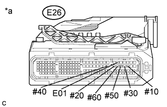 |
Disconnect the ECM connector.
Turn the engine switch on (IG).
Measure the voltage according to the value(s) in the table below.
| Tester Connection | Switch Condition | Specified Condition |
| E26-58 (#10) - E26-25 (E01) | Engine switch on (IG) | 11 to 14 V |
| E26-54 (#20) - E26-25 (E01) | Engine switch on (IG) | 11 to 14 V |
| E26-57 (#30) - E26-25 (E01) | Engine switch on (IG) | 11 to 14 V |
| E26-53 (#40) - E26-25 (E01) | Engine switch on (IG) | 11 to 14 V |
| E26-56 (#50) - E26-25 (E01) | Engine switch on (IG) | 11 to 14 V |
| E26-55 (#60) - E26-25 (E01) | Engine switch on (IG) | 11 to 14 V |
| *a | Front view of wire harness connector (to ECM) |
|
| ||||
| OK | |
|
| 11.CHECK FUEL INJECTOR OF MISFIRING CYLINDER |
Check the fuel injector assembly injection (whether fuel volume is high or low, and whether injection pattern is poor) (Click here).
|
| ||||
| OK | |
|
| 12.CHECK INTAKE SYSTEM |
Check the intake system for vacuum leaks (Click here).
|
| ||||
| OK | |
|
| 13.CHECK FUEL PRESSURE |
Check the fuel pressure .
|
| ||||
| OK | |
|
| 14.READ VALUE USING TECHSTREAM (COOLANT TEMP) |
Connect the Techstream to the DLC3.
Turn the engine switch on (IG).
Turn the Techstream on.
Enter the following menus: Powertrain / Engine / Data List / Primary / Coolant Temp.
Read the Data List twice, when the engine is both cold and warmed up.
| Techstream Display | Condition | Specified Condition |
| Coolant Temp | Cold engine | Same as ambient air temperature |
| Warm engine | Between 75 and 100°C (167 and 212°F) |
|
| ||||
| OK | |
|
| 15.READ VALUE USING TECHSTREAM (MAF) |
Connect the Techstream to the DLC3.
Start the engine.
Turn the Techstream on.
Enter the following menus: Powertrain / Engine / Data List / Primary / MAF, Coolant Temp and Engine Speed.
Allow the engine to idle until Coolant Temp reaches 75°C (167°F) or higher.
Read MAF with the engine speed at 2500 rpm.
| Techstream Display | Condition | Specified Condition |
| MAF | Shift lever position: N A/C: Off Engine Speed: 2500 rpm | Between 8 gm/sec and 19 gm/sec |
|
| ||||
| OK | |
|
| 16.CHECK VALVE TIMING (CHECK FOR LOOSE TIMING CHAIN AND JUMPED TEETH) |
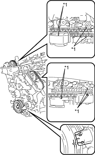 |
Remove the cylinder head cover sub-assemblies RH and LH (Click here).
Turn the crankshaft pulley, and align its groove with the "0" timing mark of the timing chain cover.
Check that the timing marks of the camshaft timing gear assemblies and camshaft timing exhaust gear assemblies are aligned with the timing marks of the bearing cap as shown in the illustration.
| *1 | Timing Mark |
|
| ||||
|
| ||||
| 17.CHECK INTAKE SYSTEM |
Check the intake system for vacuum leaks (Click here).
|
| ||||
| OK | |
|
| 18.CHECK FUEL PRESSURE |
Check the fuel pressure .
|
| ||||
| OK | |
|
| 19.READ VALUE USING TECHSTREAM (COOLANT TEMP) |
Connect the Techstream to the DLC3.
Turn the engine switch on (IG).
Turn the Techstream on.
Enter the following menus: Powertrain / Engine / Data List / Primary / Coolant Temp.
Read the Data List twice, when the engine is both cold and warmed up.
| Techstream Display | Condition | Specified Condition |
| Coolant Temp | Cold engine | Same as ambient air temperature |
| Warm engine | Between 75 and 100°C (167 and 212°F) |
|
| ||||
| OK | |
|
| 20.READ VALUE USING TECHSTREAM (MAF) |
Connect the Techstream to the DLC3.
Start the engine.
Turn the Techstream on.
Enter the following menus: Powertrain / Engine / Data List / Primary / MAF, Coolant Temp and Engine Speed.
Allow the engine to idle until Coolant Temp reaches 75°C (167°F) or higher.
Read MAF with the engine speed at 2500 rpm.
| Techstream Display | Condition | Specified Condition |
| MAF | Shift lever position: N A/C: Off Engine Speed: 2500 rpm | Between 8 gm/sec and 19 gm/sec |
|
| ||||
| OK | |
|
| 21.CHECK VALVE TIMING (CHECK FOR LOOSE TIMING CHAIN AND JUMPED TEETH) |
|
Remove the cylinder head cover sub-assemblies RH and LH (Click here).
Turn the crankshaft pulley, and align its groove with the "0" timing mark of the timing chain cover.
Check that the timing marks of the camshaft timing gear assemblies and camshaft timing exhaust gear assemblies are aligned with the timing marks of the bearing cap as shown in the illustration.
| *1 | Timing Mark |
|
| ||||
| OK | |
|
| 22.INSPECT SPARK PLUG |
Inspect the spark plug of the misfiring cylinder .
|
| ||||
| OK | |
|
| 23.CHECK FOR SPARK (SPARK TEST) |
Perform a spark test .
| NEXT | |
|
| 24.CHECK CYLINDER COMPRESSION PRESSURE |
Measure the cylinder compression pressure of the misfiring cylinder .
|
| ||||
| OK | |
|
| 25.CHECK ECM TERMINAL VOLTAGE (#10, #20, #30, #40, #50 AND/OR #60) |
|
Disconnect the ECM connector.
Turn the engine switch on (IG).
Measure the voltage according to the value(s) in the table below.
| Tester Connection | Switch Condition | Specified Condition |
| E26-58 (#10) - E26-25 (E01) | Engine switch on (IG) | 11 to 14 V |
| E26-54 (#20) - E26-25 (E01) | Engine switch on (IG) | 11 to 14 V |
| E26-57 (#30) - E26-25 (E01) | Engine switch on (IG) | 11 to 14 V |
| E26-53 (#40) - E26-25 (E01) | Engine switch on (IG) | 11 to 14 V |
| E26-56 (#50) - E26-25 (E01) | Engine switch on (IG) | 11 to 14 V |
| E26-55 (#60) - E26-25 (E01) | Engine switch on (IG) | 11 to 14 V |
| *a | Front view of wire harness connector (to ECM) |
|
| ||||
| OK | |
|
| 26.CHECK FUEL INJECTOR OF MISFIRING CYLINDER |
Check the fuel injector assembly injection (whether fuel volume is high or low, and whether injection pattern is poor) (Click here).
|
| ||||
| OK | |
|
| 27.CHECK HARNESS AND CONNECTOR (MASS AIR FLOW METER SUB-ASSEMBLY CONNECTOR CONNECTION) |
Check the connection and terminal contact pressure of connectors and wire harnesses between the mass air flow meter sub-assembly and ECM (Click here).
| NEXT | |
|
| 28.CHECK WHETHER DTC OUTPUT RECURS (MISFIRE DTCS) |
Connect the Techstream to the DLC3.
Turn the engine switch on (IG).
Turn the Techstream on.
Clear the DTCs (Click here).
Turn the engine switch off and wait for at least 30 seconds.
Start the engine and warm it up.
Turn the Techstream on.
Drive the vehicle in accordance with the driving pattern described in Confirmation Driving Pattern.
Enter the following menus: Powertrain / Engine / Utility / All Readiness.
Input the DTC: P0300, P0301, P0302, P0303, P0304, P0305 or P0306.
Check the DTC judgment result.
| Result | Proceed to |
| ABNORMAL (DTC P0300, P0301, P0302, P0303, P0304, P0305 and/or P0306 is output) | A |
| NORMAL (DTC is not output) | B |
|
| ||||
| A | |
|
| 29.CHECK HARNESS AND CONNECTOR (MASS AIR FLOW METER SUB-ASSEMBLY - ECM) |
Disconnect the mass air flow meter sub-assembly connector.
Disconnect the ECM connector.
Measure the resistance according to the value(s) in the table below.
| Tester Connection | Condition | Specified Condition |
| E14-5 (VG) - E26-98 (VG) | Always | Below 1 Ω |
| E14-4 (E2G) - E26-130 (E2G) | Always | Below 1 Ω |
| E14-5 (VG) or E26-98 (VG) - Body ground | Always | 10 kΩ or higher |
|
| ||||
| OK | |
|
| 30.REPLACE MASS AIR FLOW METER SUB-ASSEMBLY |
Replace the mass air flow meter sub-assembly (Click here).
| NEXT | |
|
| 31.CONFIRM WHETHER MALFUNCTION HAS BEEN SUCCESSFULLY REPAIRED |
Connect the Techstream to the DLC3.
Turn the engine switch on (IG).
Turn the Techstream on.
Clear the DTCs (Click here).
Turn the engine switch off and wait for at least 30 seconds.
Start the engine and warm it up.
Turn the Techstream on.
Drive the vehicle in accordance with the driving pattern described in Confirmation Driving Pattern.
Enter the following menus: Powertrain / Engine / Utility / All Readiness.
Input the DTC: P0300, P0301, P0302, P0303, P0304, P0305 or P0306.
Check the DTC judgment result.
| Result | Proceed to |
| NORMAL (DTC is not output) | A |
| ABNORMAL (DTC P0300, P0301, P0302, P0303, P0304, P0305 and/or P0306 is output) | B |
|
| ||||
| A | ||
 | ||
| ||
| 32.CHECK FUEL LINE |
Check the fuel lines for leaks or blockage.
|
| ||||
| OK | ||
| ||
| ||
