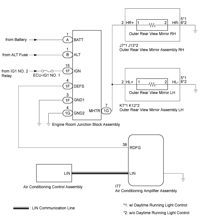
POWER MIRROR CONTROL SYSTEM > Mirror Heater does not Operate with Rear Defogger Switch |
| 1.PERFORM ACTIVE TEST USING TECHSTREAM |
Connect the Techstream to the DLC3.
Turn the ignition switch to ON.
Turn the Techstream on.
Enter the following menus: Body Electrical / Air Conditioner / Active Test.
Perform an Active Test according to the display on the Techstream.
| Tester Display | Test Part | Control Range | Diagnostic Note |
| Defogger Relay (Rear) | Mirror heater | OFF/ON | - |
| Result | Proceed to |
| Mirror heater operations on both mirrors are not normal | A |
| Mirror heater operation on RH side mirror is not normal | B |
| Mirror heater operation on LH side mirror is not normal | C |
|
| ||||
|
| ||||
| A | |
 |
| 2.CHECK REAR WINDOW DEFOGGER SYSTEM |
Check the rear window defogger operation (Click here).
|
| ||||
| OK | |
|
| 3.CHECK ENGINE ROOM JUNCTION BLOCK ASSEMBLY |
Using a voltmeter, check the signal reading of the engine room junction block assembly (Click here).
|
| ||||
| OK | |
|
| 4.CHECK HARNESS AND CONNECTOR (ENGINE ROOM JUNCTION BLOCK ASSEMBLY - POWER SOURCE AND BODY GROUND) |
Remove the engine room junction block assembly from the engine room relay block and junction block assembly.
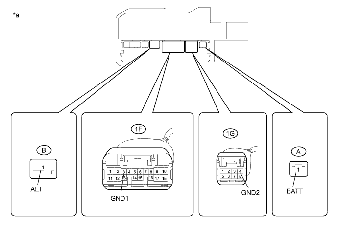
Measure the voltage according to the value(s) in the table below.
| Tester Connection | Condition | Specified Condition |
| A-1 (BATT) - Body ground | Always | 11 to 14 V |
| B-1 (ALT) - Body ground | Always | 11 to 14 V |
Measure the resistance according to the value(s) in the table below.
| Tester Connection | Condition | Specified Condition |
| 1F-3 (GND1) - Body ground | Always | Below 1 Ω |
| 1G-4 (GND2) - Body ground | Always | Below 1 Ω |
| *a | Component without engine room junction block assembly (Engine Room Relay Block and Junction Block Assembly) | - | - |
|
| ||||
| OK | |
|
| 5.CHECK HARNESS AND CONNECTOR (OUTER REAR VIEW MIRROR ASSEMBLY - ENGINE ROOM JUNCTION BLOCK ASSEMBLY) |
Disconnect the 1G connector from the engine room junction block assembly.
Disconnect the J7*1 or J13*2 connector from the outer rear view mirror assembly RH.
Disconnect the K7*1 or K12*2 connector from the outer rear view mirror assembly LH.
Measure the resistance according to the value(s) in the table below
| Tester Connection | Condition | Specified Condition |
| 1G-7 (MHTR) - J7-2 (HR+)*1 1G-7 (MHTR) - J13-2 (HR+)*2 | Always | Below 1 Ω |
| 1G-7 (MHTR) - K7-2 (HR+)*1 1G-7 (MHTR) - K12-2 (HR+)*2 | Always | Below 1 Ω |
|
| ||||
| OK | ||
 | ||
| ||
| 6.CHECK HARNESS AND CONNECTOR (ENGINE ROOM JUNCTION BLOCK ASSEMBLY - OUTER REAR VIEW MIRROR ASSEMBLY RH - BODY GROUND) |
Disconnect the 1G connector from the engine room junction block assembly .
Disconnect the J7*1 or J13*2 connector from the outer rear view mirror assembly RH.
Measure the resistance according to the value(s) in the table below.
| Tester Connection | Condition | Specified Condition |
| 1G-7 (MHTR) - J7-2 (MR+)*1 1G-7 (MHTR) - J13-2 (MR+)*2 | Always | Below 1 Ω |
| J7-5 (HR-) - Body Ground*1 J13-8 (HR-) - Body Ground*2 | Always | Below 1 Ω |
|
| ||||
| OK | |
|
| 7.INSPECT OUTER REAR VIEW MIRROR RH |
Remove the outer rear view mirror RH (Click here).
Inspect the outer rear view mirror RH (Click here).
|
| ||||
| OK | ||
| ||
| ||
| 8.CHECK HARNESS AND CONNECTOR (ENGINE ROOM JUNCTION BLOCK ASSEMBLY - OUTER REAR VIEW MIRROR ASSEMBLY LH - BODY GROUND) |
Disconnect the 1G connector from the engine room junction block assembly.
Disconnect the K7*1 or K12*2 connector from the outer rear view mirror assembly LH.
Measure the resistance according to the value(s) in the table below.
| Tester Connection | Condition | Specified Condition |
| 1G-7 (MHTR) - K7-2 (HL+)*1 1G-7 (MHTR) - K12-2 (HL+)*2 | Always | Below 1 Ω |
| K7-5 (HL-) - Body ground*1 K12-8 (HL-) - Body ground*2 | Always | Below 1 Ω |
|
| ||||
| OK | |
|
| 9.INSPECT OUTER REAR VIEW MIRROR LH |
Remove the outer rear view mirror LH (Click here).
Inspect the outer rear view mirror LH (Click here).
|
| ||||
| OK | ||
| ||
| ||

