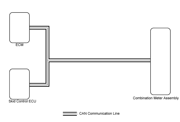
METER / GAUGE SYSTEM > Fuel Economy Meter Malfunction |
| 1.CHECK CAN COMMUNICATION SYSTEM |
Check if a CAN communication DTC is output (Click here).
| Result | Proceed to |
| CAN communication DTC is not output. | A |
| CAN communication DTC is output. | B |
|
| ||||
| A | |
 |
| 2.PERFORM ACTIVE TEST USING TECHSTREAM (FUEL CONSUMPTION METER OPERATION) |
Connect the Techstream to the DLC3.
Turn the ignition switch to ON.
Turn the Techstream on.
Enter following menus: Body Electrical / Combination Meter / Active Test.
Check the operation by referring to the table below.
| Tester Display | Test Part | Control Range | Diagnostic Note |
| Fuel Consumption Meter Operation | Fuel receiver gauge | MIN, 1/4, 1/2, 3/4, MAX | - |
|
| ||||
| OK | |
|
| 3.READ VALUE USING TECHSTREAM (VEHICLE SPEED, INJECTION VOLUM) |
Connect the Techstream to the DLC3.
Turn the ignition switch to ON.
Turn the Techstream on.
Enter the following menus:
for ABS/VSC/TRAC: Chassis / ABS/VSC/TRAC / Data List.
for Engine and ECT: Powertrain / Engine and ECT / Data List.
Check the values by referring to the table below.
| Tester Display | Measurement Item/Range | Normal Condition | Diagnostic Note |
| Vehicle Speed | Maximum wheel speed sensor reading/Min.: 0 km/h (0 mph), Max.: 326 km/h (202 mph) | Vehicle stopped: 0 km/h (0 mph) | When driving at constant speed: No large fluctuations |
| Tester Display | Measurement Item/Range | Normal Condition | Diagnostic Note |
| Injection Volume (Cylinder 1) | Injection volume (cylinder 1)/Min.: 0 ml, Max.: 2.047 ml | 0 to 0.5 ml |
|
Results of real-vehicle check:
| |||
| Result | Proceed to |
| The data list values displayed on the Techstream is within the normal condition range. | A |
| The data list values displayed on the Techstream differs from the normal condition range. (ABS/VSC/TRAC) | B |
| The data list values displayed on the Techstream differs from the normal condition range (for 2AR-FE). (Engine and ECT) | C |
| The data list values displayed on the Techstream differs from the normal condition range (for 2GR-FE). (Engine and ECT) | D |
|
| ||||
|
| ||||
|
| ||||
| A | |
|
| 4.REPLACE BRAKE ACTUATOR ASSEMBLY |
Replace the brake actuator assembly with a new or a known good one (Click here).
| Result | Proceed to |
| The operation of the fuel economy meter returns to normal. | A |
| The operation of the fuel economy meter does not return to normal. | B |
|
| ||||
| A | ||
 | ||
| ||
| 5.REPLACE ECM |
Replace the ECM with a new or a known good one (Click here for 2AR-FE, Click here for 2GR-FE).
| Result | Proceed to |
| The operation of the fuel economy meter returns to normal. | A |
| The operation of the fuel economy meter does not return to normal. | B |
|
| ||||
| A | ||
| ||
| ||

