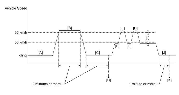
DTC P219A Bank 1 Air-Fuel Ratio Imbalance |
| DTC No. | DTC Detection Condition | Trouble Area |
| P219A | The difference in air fuel ratios between the cylinders exceeds the threshold (2 trip detection logic). |
|
| Related DTCs | P219A: Air fuel ratio cylinder imbalance monitor |
| Required Sensors/Components (Main) | Air fuel ratio sensor Crankshaft position sensor |
| Required Sensors/Components (Related) | Mass air flow meter sub-assembly Engine coolant temperature sensor Vehicle speed sensor |
| Frequency of Operation | Once per driving cycle |
| Duration | 10 seconds: Air fuel ratio sensor monitoring method 30 seconds: Crankshaft position sensor monitoring method |
| MIL Operation | 2 driving cycles |
| Sequence of Operation | None |
| Monitor runs whenever the following DTCs are not stored | P0010 (VVT oil control valve) P0011 (VVT system - advance) P0012 (VVT system - retard) P0013 (Exhaust VVT oil control valve) P0014 (Exhaust VVT system - advance) P0015 (Exhaust VVT system - retard) P0016 (VVT system - misalignment) P0017 (Exhaust VVT system - misalignment) P0031, P0032, P101D (Air fuel ratio sensor heater) P0102, P0103 (Mass air flow meter) P0115, P0117, P0118 (Engine coolant temperature sensor) P0120, P0121, P0122, P0123, P0220, P0222, P0223, P2135 (Throttle position sensor) P0125 (Insufficient coolant temperature for closed loop fuel control) P0327, P0328 (Knock control sensor) P0335 (Crankshaft position sensor) P0340, P0342, P0343 (Camshaft position sensor) P0351 - P0354 (Igniter) P0365, P0367, P0368 (Exhaust camshaft position sensor) P0500 (Vehicle speed sensor) |
| Air fuel ratio sensor status | Activated |
| Engine speed | 1600 rpm or higher, and less than 2400 rpm |
| Engine coolant temperature | 75°C (167°F) or higher |
| Atmospheric pressure | 76 kPa(abs) [570 mmHg(abs)] or higher |
| Fuel system status | Closed loop |
| Mass air flow | 20 gm/sec or more, and less than 28 gm/sec |
| Vehicle speed | Less than 3 km/h (1.875 mph) |
| Engine speed | 450 rpm or higher, and less than 1000 rpm |
| Engine coolant temperature | 75°C (167°F) or higher |
| Air fuel ratio sensor status | Activated |
| Fuel system status | Closed loop |
| Battery voltage | 11 V or higher |
| Air fuel ratio sensor monitoring method criteria (rich side imbalance) | 0.0596 or more |
| Crankshaft position sensor monitoring method criteria (lean side imbalance) | 1.0 or more |
| Monitor ID | Test ID | Scaling | Unit | Description |
| $81 | $81 | Multiply by 0.00003 | No dimension | Monitoring method using A/F sensor |
| Monitor ID | Test ID | Scaling | Unit | Description |
| $81 | $82 | Multiply by 0.001 | No dimension | Monitoring method using crank angle sensor |
| Techstream Display | Description |
| NORMAL |
|
| ABNORMAL |
|
| INCOMPLETE |
|
| N/A |
|
| 1.CHECK ANY OTHER DTCS OUTPUT (IN ADDITION TO DTC P219A) |
Connect the Techstream to the DLC3.
Turn the ignition switch to ON.
Turn the Techstream on.
Enter the following menus: Powertrain / Engine and ECT / Trouble Codes.
Read the DTCs.
| Result | Proceed to |
| DTC P219A is output | A |
| DTC P219A and other DTCs are output | B |
|
| ||||
| A | |
 |
| 2.READ VALUE USING TECHSTREAM (FREEZE FRAME DATA) |
Connect the Techstream to the DLC3.
Turn the ignition switch to ON.
Using the Techstream, confirm the vehicle conditions recorded in the freeze frame data which were present when the DTC was stored (Click here).
| DTC stored during idling | It is possible to conclude that the problem was detected due to a "lean imbalance" (detected using crankshaft speed variation). |
| DTC stored while vehicle being driven | It is possible to conclude that the problem was detected due to a "rich imbalance" (detected using the air fuel ratio sensor). |
| NEXT | |
|
| 3.READ VALUE USING TECHSTREAM (MONITOR RESULT) |
Connect the Techstream to the DLC3.
Turn the ignition switch to ON.
Turn the Techstream on.
Drive the vehicle in accordance with the driving pattern described in Confirmation Driving Pattern.
Enter the following menus: Powertrain / Engine and ECT / Monitor / Current Monitor / Fuel System / Details / A/F SENSOR DETERMINATION B1 and ENGINE SPEED FLUCTUATION AVERAGE B1.
Check the Test Result (A/F SENSOR DETERMINATION B1 and ENGINE SPEED FLUCTUATION AVERAGE B1).
| Result | Proceed to |
| A/F SENSOR DETERMINATION is Fail | A |
| A/F SENSOR DETERMINATION and ENGINE SPEED FLUCTUATION AVERAGE are Fail | B |
| ENGINE SPEED FLUCTUATION AVERAGE is Fail | B* |
|
| ||||
| A | |
|
| 4.PERFORM ACTIVE TEST USING TECHSTREAM (CONTROL THE INJECTION VOLUME) |
Connect the Techstream to the DLC3.
Start the engine.
Turn the Techstream on.
Warm up the engine.
Enter the following menus: Powertrain / Engine and ECT / Active Test / Control the Injection Volume / Gas Misfire / Cylinder #1 to #4 Misfire Count.
Perform the Control the Injection Volume operation with the engine idling.
Check the misfire counts ("Cylinder #1 Misfire Count" to "Cylinder #4 Misfire Count") while decreasing the injection volume in 5% increments.
| NEXT | |
|
| 5.CHECK FOR EXHAUST GAS LEAK |
Check for exhaust gas leaks.
|
| ||||
| OK | |
|
| 6.CHECK INTAKE SYSTEM |
Check the intake system for vacuum leaks .
|
| ||||
| OK | |
|
| 7.INSPECT SPARK PLUG |
Inspect the spark plug of the cylinder causing the imbalance .
|
| ||||
| OK | |
|
| 8.CHECK FOR SPARK (SPARK TEST) |
Perform a spark test .
| NEXT | |
|
| 9.CHECK CYLINDER COMPRESSION PRESSURE |
Measure the cylinder compression pressure of the misfiring cylinder .
|
| ||||
| OK | |
|
| 10.CHECK TERMINAL VOLTAGE (POWER SOURCE OF FUEL INJECTOR ASSEMBLY) |
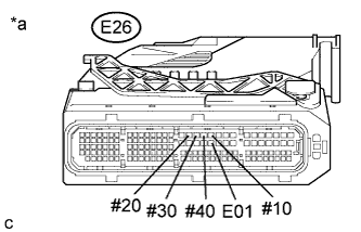 |
Disconnect the ECM connector.
Turn the ignition switch to ON.
Measure the voltage according to the value(s) in the table below.
| Tester Connection | Switch Condition | Specified Condition |
| E26-20 (#10) - E26-50 (E01) | Ignition switch ON | 11 to 14 V |
| E26-17 (#20) - E26-50 (E01) | Ignition switch ON | 11 to 14 V |
| E26-18 (#30) - E26-50 (E01) | Ignition switch ON | 11 to 14 V |
| E26-19 (#40) - E26-50 (E01) | Ignition switch ON | 11 to 14 V |
| *a | Front view of wire harness connector (to ECM) |
|
| ||||
| OK | |
|
| 11.CHECK FUEL INJECTOR ASSEMBLY OF CYLINDER CAUSING IMBALANCE |
Check the fuel injector injection [whether fuel volume is high or low, and whether injection pattern is poor] (Click here).
|
| ||||
| OK | |
|
| 12.CHECK FOR CAUSE OF FAILURE |
If the cause of the problem has not been found even after performing the troubleshooting procedure, perform the inspection below.
Check the intake valve for deposits.
| NEXT | |
|
| 13.CONFIRM WHETHER MALFUNCTION HAS BEEN SUCCESSFULLY REPAIRED |
Connect the Techstream to the DLC3.
Turn the ignition switch to ON.
Turn the Techstream on.
Clear the DTCs.
Turn the ignition switch off and wait for at least 30 seconds.
Turn the ignition switch to ON.
Turn the Techstream on.
Drive the vehicle in accordance with the driving pattern described in Confirmation Driving Pattern.
Enter the following menus: Powertrain / Engine and ECT / Trouble Codes.
Check for DTCs.
| NEXT | ||
 | ||
| ||

