HYBRID / BATTERY CONTROL HV RELAY ASSEMBLY INSTALLATION
PROCEDURE

 G92Z0
1.INSTALL HYBRID BATTERY JUNCTION BLOCK ASSEMBLY
- CAUTION:
-
Wear insulated gloves.
Install the hybrid battery junction block assembly with the 3 bolts.
- Torque:
- 7.5 N*m (76 kgf*cm, 66 in.*lbf)
Connect the connector to the hybrid battery junction block assembly.
- NOTICE:
-
The connector should be connected securely.
Using an insulated tool, install the 2 bolts.
- Torque:
- 5.4 N*m (55 kgf*cm, 48 in.*lbf)
- NOTICE:
-
Be sure to use a torque wrench to tighten the bolts.
Connect the terminal cover.
- NOTICE:
-
The terminal cover should be connected securely.
G920Q
2.INSTALL NO. 1 HYBRID BATTERY SHIELD SUB-ASSEMBLY
- CAUTION:
-
Wear insulated gloves.
Install the No. 1 hybrid battery shield sub-assembly with the bolt and 3 nuts.
- Torque:
- 7.5 N*m (76 kgf*cm, 66 in.*lbf)
Connect the connector.
- NOTICE:
-
The connector should be connected securely.
82164C
3.CONNECT NO. 4 FLOOR WIRE
- CAUTION:
-
Wear insulated gloves.
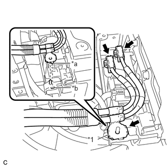
| *1 | Shielded Wire Ground |
| *a | Claw |
| *b | Hole |
Connect the 2 connectors.
Connect the shielded wire ground.
- NOTICE:
- ·
Make sure that the ends of the No. 4 floor wire do not cross over each other.
·The connector should be connected securely.
·Be sure to align the claw of the shielded wire ground with the hole.
·Be sure to install the shielded wire ground in the correct direction.
G92Q6
4.INSTALL NO. 4 HYBRID BATTERY SHIELD PANEL
- CAUTION:
-
Wear insulated gloves.
Install the No. 4 hybrid battery shield panel with the bolt and 2 nuts.
- Torque:
- 7.5 N*m (76 kgf*cm, 66 in.*lbf)
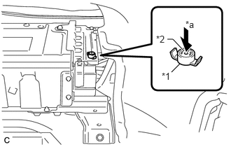
| *1 | Battery Cover Lock Striker |
| *2 | Button |
| *a | Push |
Install the battery cover lock striker, then push the button to lock it.
64272B
5.INSTALL ROOM PARTITION BOARD LH
6.INSTALL REAR SIDE SEATBACK ASSEMBLY RH
7.INSTALL REAR SEATBACK ASSEMBLY RH
72693
8.INSTALL REAR SEAT CUSHION LOCK HOOK
9.INSTALL REAR SEAT CUSHION ASSEMBLY
G3834
10.INSTALL SERVICE PLUG GRIP