2AR-FXE FUEL FUEL PUMP INSTALLATION
PROCEDURE

 77020A
1.INSTALL FUEL SUCTION TUBE WITH PUMP AND GAUGE ASSEMBLY
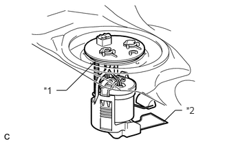
| *1 | Fuel Suction Tube Set Gasket |
| *2 | Suction Filter |
Install a new fuel suction tube set gasket to the fuel suction tube.
Install the fuel suction tube with pump and gauge assembly to the fuel tank.
- NOTICE:
- ·
Do not damage the suction filter.
·Be careful that the arm of the sender gauge does not bend.
77168A
2.INSTALL FUEL TANK VENT TUBE SET PLATE
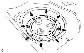
| *a | Mark |
Align the mark of the set plate with the fuel suction tube.
Install the set plate with the 8 bolts.
- Torque:
- 6.0 N*m (61 kgf*cm, 53 in.*lbf)
77209B
3.CONNECT FUEL PUMP TUBE SUB-ASSEMBLY
Push the fuel tube joint onto the plug of the fuel suction plate, then install the tube joint clip.
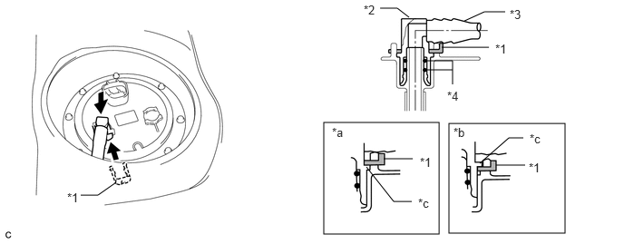
| *1 | Tube Joint Clip | *2 | Fuel Tube Joint |
| *3 | Fuel Pump Tube | *4 | O-ring |
| *a | Correct | *b | Incorrect |
| *c | Collar | - | - |
- NOTICE:
- ·
Check that there are no scratches or foreign matter around the connected part of the fuel tube joint and plug before performing this work.
·Check that the fuel tube joint is securely inserted to the end.
·Check that the tube joint clip is on the collar of the fuel tube joint.
·After installing the tube joint clip, check that the fuel tube joint cannot be pulled out.
Connect the fuel pump connector.
4.CONNECT CABLE TO NEGATIVE AUXILIARY BATTERY TERMINAL
- NOTICE:
-
When disconnecting the cable, some systems need to be initialized after the cable is reconnected.
-
Click hereGeneral>INTRODUCTION>REPAIR INSTRUCTION>INITIALIZATION
64718C
5.INSTALL LUGGAGE TRIM SERVICE HOLE COVER
6.INSPECT FOR FUEL LEAK
58325E
7.INSTALL REAR FLOOR SERVICE HOLE COVER
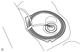

|
Butyl Tape |
Install the rear floor service hole cover with new butyl tape.
72693
8.INSTALL REAR SEAT CUSHION LOCK HOOK
9.INSTALL REAR SEAT CUSHION ASSEMBLY