HYBRID / BATTERY CONTROL HYBRID CONTROL SYSTEM P3004-800 High Voltage Power Resource P3004-801 High Voltage Power Resource
DESCRIPTION
Refer to the description for DTC P0AE6-225 (See page Engine / Hybrid System>HYBRID / BATTERY CONTROL>HYBRID CONTROL SYSTEM>P0AE6-225).
| DTC No. | Detection Item | DTC Detection Condition | Trouble Area | MIL | Warning Indicate |
|---|---|---|---|---|---|
| P3004-800 | High Voltage Power Resource | Excessive overcurrent occurs during precharge (time from when SMRP turns on until when SMRG turns on). | ·
Wire harness or connector ·
No. 4 engine wire ·
Compressor with motor assembly ·
Inverter with converter assembly ·
Hybrid battery junction block assembly ·
No. 4 floor wire ·
Power management control ECU |
Does not come on | Master Warning Light:
Comes on |
| P3004-801 | High Voltage Power Resource | Minimal overcurrent occurs during precharge (time from when SMRP turns on until when SMRG turns on). | ·
Wire harness or connector ·
No. 4 engine wire ·
Compressor with motor assembly ·
Inverter with converter assembly ·
Hybrid battery junction block assembly ·
No. 4 floor wire ·
Power management control ECU |
Does not come on | Master Warning Light:
Comes on |
WIRING DIAGRAM
Refer to the wiring diagram for DTC P0A08-264 (See page Engine / Hybrid System>HYBRID / BATTERY CONTROL>HYBRID CONTROL SYSTEM>P0A08-264).
Refer to the wiring diagram for DTC P0AA6-526 (See page Engine / Hybrid System>HYBRID / BATTERY CONTROL>HYBRID CONTROL SYSTEM>P0AA6-526 ).
Refer to the wiring diagram for DTC P0AE6-225 (See page Engine / Hybrid System>HYBRID / BATTERY CONTROL>HYBRID CONTROL SYSTEM>P0AE6-225).
CAUTION / NOTICE / HINT
- CAUTION:
- ·
Before inspecting the high-voltage system or disconnecting the low voltage connector of the inverter with converter assembly, take safety precautions such as wearing insulated gloves and removing the service plug grip to prevent electrical shocks. After removing the service plug grip, put it in your pocket to prevent other technicians from accidentally reconnecting it while you are working on the high-voltage system.
·After removing the service plug grip, wait for at least 10 minutes before touching any of the high-voltage connectors or terminals. After waiting for 10 minutes, check the voltage at the terminals in the inspection point in the inverter with converter assembly. The voltage should be 0 V before beginning work (See pageEngine / Hybrid System>HYBRID / BATTERY CONTROL>HYBRID CONTROL SYSTEM>PRECAUTION).
- HINT:
-
Waiting for at least 10 minutes is required to discharge the high-voltage capacitor inside the inverter with converter assembly.
- NOTICE:
-
After turning the power switch off, waiting time may be required before disconnecting the cable from the negative (-) auxiliary battery terminal. Therefore, make sure to read the disconnecting the cable from the negative (-) auxiliary battery terminal notices before proceeding with work (See page ).
PROCEDURE
Connect the intelligent tester to the DLC3.
Turn the power switch on (IG).
Enter the following menus: Powertrain / Hybrid Control / DTC.
Check for DTCs.
- Powertrain > Hybrid Control > Trouble Codes
- 50001 236
- Result:
Result Proceed to P3004-800 or P3004-801 only is output. A DTCs shown in Table 1 are output simultaneously. B DTCs shown in Table 2 are output simultaneously. C
| DTC No. | Relevant Diagnosis |
|---|---|
| P0A09-265 | DC/DC Converter Status Circuit Low Input |
| P0A10-263 | DC/DC Converter Status Circuit High Input |
| DTC No. | Relevant Diagnosis |
|---|---|
| P0ABF-123 | Hybrid Battery Pack Current Sensor Circuit |
| P0AC0-123 | Hybrid Battery Pack Current Sensor Circuit Range / Performance |
| P0AC1-123 | Hybrid Battery Pack Current Sensor Circuit Low |
| P0AC2-123 | Hybrid Battery Pack Current Sensor Circuit High |
| P0AFC-123 | Hybrid Battery Pack Sensor Module |
| P0B3D-123 | Hybrid Battery Voltage Sensor "A" Circuit Low |
| P0B42-123 | Hybrid Battery Voltage Sensor "B" Circuit Low |
| P0B47-123 | Hybrid Battery Voltage Sensor "C" Circuit Low |
| P0B4C-123 | Hybrid Battery Voltage Sensor "D" Circuit Low |
| P0B51-123 | Hybrid Battery Voltage Sensor "E" Circuit Low |
| P0B56-123 | Hybrid Battery Voltage Sensor "F" Circuit Low |
| P0B5B-123 | Hybrid Battery Voltage Sensor "G" Circuit Low |
| P0B60-123 | Hybrid Battery Voltage Sensor "H" Circuit Low |
| P0B65-123 | Hybrid Battery Voltage Sensor "I" Circuit Low |
| P0B6A-123 | Hybrid Battery Voltage Sensor "J" Circuit Low |
| P0B6F-123 | Hybrid Battery Voltage Sensor "K" Circuit Low |
| P0B74-123 | Hybrid Battery Voltage Sensor "L" Circuit Low |
| P0B79-123 | Hybrid Battery Voltage Sensor "M" Circuit Low |
| P0B7E-123 | Hybrid Battery Voltage Sensor "N" Circuit Low |
| P0B83-123 | Hybrid Battery Voltage Sensor "O" Circuit Low |
| P0B88-123 | Hybrid Battery Voltage Sensor "P" Circuit Low |
| P0B8D-123 | Hybrid Battery Voltage Sensor "Q" Circuit Low |
| P0B92-123 | Hybrid Battery Voltage Sensor "R" Circuit Low |
| P308A-123 | Hybrid Battery Voltage Sensor All Circuits Low |
| U029A-123 | Lost Communication with Hybrid Battery Pack Sensor Module |
- HINT:
-
P3004-800 or P3004-801 may be output due to a malfunction which causes the DTCs in the table above to be output. In this case, first troubleshoot the output DTCs in the table above. Then, perform a reproduction test to check that no DTCs are output.
Turn the power switch off.
A
B
Click hereEngine / Hybrid System>HYBRID / BATTERY CONTROL>HYBRID CONTROL SYSTEM>DIAGNOSTIC TROUBLE CODE CHART
C
Click hereEngine / Hybrid System>HYBRID / BATTERY CONTROL>HYBRID BATTERY SYSTEM>DIAGNOSTIC TROUBLE CODE CHART
(Click here Engine / Hybrid System>HYBRID / BATTERY CONTROL>HYBRID CONTROL SYSTEM>P0340-886)
- Result:
Proceed to OK NG
OK
NG
- CAUTION:
-
Be sure to wear insulated gloves.
Check that the service plug grip is not installed.
- NOTICE:
-
After removing the service plug grip, do not turn the power switch on (READY), unless instructed by the repair manual because this may cause a malfunction.
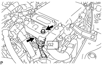
Disconnect connector G2 of the No. 4 engine wire (air conditioning harness) from the inverter with converter assembly.
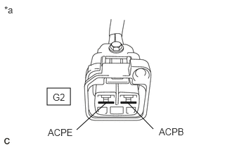
| *a | No. 4 engine wire (Air Conditioning Harness)
(Inverter with Converter Assembly Side) |
Measure the resistance according to the value(s) in the table below.
- Standard Resistance:
Tester Connection
(Tester Probe Polarity)Switch Condition Specified Condition G2-1 (ACPE) (Negative probe) - G2-2 (ACPB) (Positive probe) Power switch off 100 kΩ or higher
- NOTICE:
- ·
Do not use a megohmmeter.
·Read the resistance after the value has stabilized.
- HINT:
-
The polarities of the tester probes may differ depending on the tester. Use the current output probe of the tester as the positive probe for this measurement. To determine the polarity, use another voltmeter to confirm the current output probe of the tester. When measuring the output of the tester, the voltmeter positive probe indicates the tester current output probe.
Connect the No. 4 engine wire (air conditioning harness) to the inverter with converter assembly.
- Result:
Proceed to OK NG
OK
NG
- CAUTION:
-
Be sure to wear insulated gloves.
Check that the service plug grip is not installed.
- NOTICE:
-
After removing the service plug grip, do not turn the power switch on (READY), unless instructed by the repair manual because this may cause a malfunction.
Disconnect connector A13 from the inverter with converter assembly.
Disconnect connector A38 from power management control ECU.
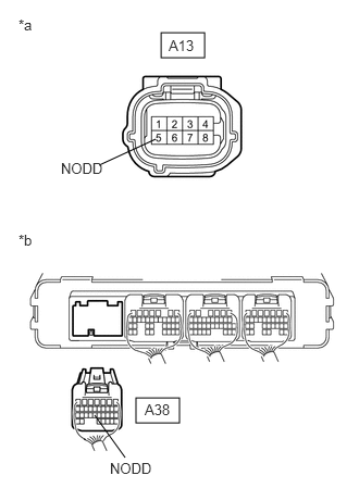
| *a | Front view of wire harness connector
(to Inverter with Converter Assembly) |
| *b | Rear view of wire harness connector
(to Power Management Control ECU) |
Measure the resistance according to the value(s) in the table below.
- Standard Resistance (Check for Open):
Tester Connection Switch Condition Specified Condition A13-5 (NODD) - A38-23 (NODD) Power switch off Below 1 Ω
- Standard Resistance (Check for Short):
Tester Connection Switch Condition Specified Condition A13-5 (NODD) or A38-23 (NODD) - Body ground and other terminals Power switch off 10 kΩ or higher
Connect the power management control ECU connector.
Connect the inverter with converter assembly connector.
- Result:
Proceed to OK NG
OK
NG
- CAUTION:
-
Be sure to wear insulated gloves.
Check that the service plug grip is not installed.
- NOTICE:
-
After removing the service plug grip, do not turn the power switch on (READY), unless instructed by the repair manual because this may cause a malfunction.
Connect the cable to the negative (-) auxiliary battery terminal.
Turn the power switch on (IG).
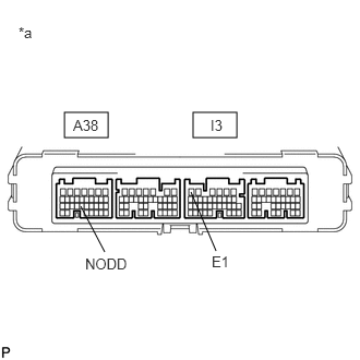
| *a | Component without harness connected
(Power Management Control ECU) |
Measure the voltage according to the value(s) in the table below.
- Standard Voltage:
Tester Connection Switch Condition Specified Condition A38-23 (NODD) - I3-6 (E1) Power switch on (IG) Less than 1.5 V
Turn the power switch off.
Disconnect the cable from the negative (-) auxiliary battery terminal.
- Result:
Proceed to OK NG
OK
NG
- CAUTION:
-
Be sure to wear insulated gloves.
Check that the service plug grip is not installed.
- NOTICE:
-
After removing the service plug grip, do not turn the power switch on (READY), unless instructed by the repair manual because this may cause a malfunction.
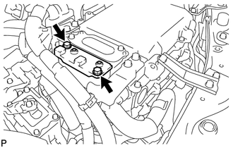
Remove the connector cover assembly from the inverter with converter assembly.
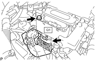
Disconnect connector Q1 of the No. 4 floor wire from the inverter with converter assembly.
Remove the No. 4 hybrid battery shield panel
(Click here Engine / Hybrid System>HYBRID / BATTERY CONTROL>HV RELAY ASSEMBLY>REMOVAL).
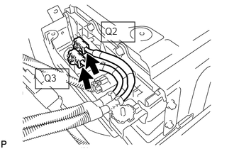
Measure the resistance according to the value(s) in the table below.
- Standard Resistance:
Tester Connection Switch Condition Specified Condition Q2-1 (CBI) - Q3-1 (CEI) Power switch off 10 kΩ or higher
Install the No. 4 hybrid battery shield panel.
Connect the No. 4 floor wire.
Install the connector cover assembly.
- Result:
Proceed to OK NG
OK
NG
- CAUTION:
-
Be sure to wear insulated gloves.
Check that the service plug grip is not installed.
- NOTICE:
-
After removing the service plug grip, do not turn the power switch on (READY), unless instructed by the repair manual because this may cause a malfunction.
Disconnect connector G2 of the No. 4 engine wire (air conditioning harness) from the inverter with converter assembly.
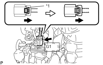
| *1 | Green Lock |
Disconnect connector G1 of the No. 4 engine wire (air conditioning harness) from the compressor with motor assembly.
| *a | No. 4 engine wire (Air Conditioning Harness)
(Inverter with Converter Assembly Side) |
Measure the resistance according to the value(s) in the table below.
- Standard Resistance:
Tester Connection Switch Condition Specified Condition G2-1 (ACPE) - G2-2 (ACPB) Power switch off 10 kΩ or higher
Connect the No. 4 engine wire (air conditioning harness) to the compressor with motor assembly.
Connect the No. 4 engine wire (air conditioning harness) to the inverter with converter assembly.
- Result:
Proceed to OK NG
OK
NG
- CAUTION:
-
Be sure to wear insulated gloves.
Check that the service plug grip is not installed.
- NOTICE:
-
After removing the service plug grip, do not turn the power switch on (READY), unless instructed by the repair manual because this may cause a malfunction.
Remove the No. 4 hybrid battery shield panel
(Click here Engine / Hybrid System>HYBRID / BATTERY CONTROL>HV RELAY ASSEMBLY>REMOVAL).
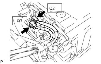
Disconnect connector Q2 and connector Q3 of the No. 4 floor wire from the hybrid battery junction block assembly.
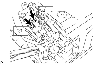
Measure the resistance according to the value(s) in the table below.
- Standard Resistance:
Tester Connection Switch Condition Specified Condition Q3-1 (CEI) - Q2-1 (CBI) Power switch off 10 kΩ or higher
Connect the No. 4 floor wire.
Install the No. 4 hybrid battery shield panel.
- Result:
Proceed to OK NG
OK
NG