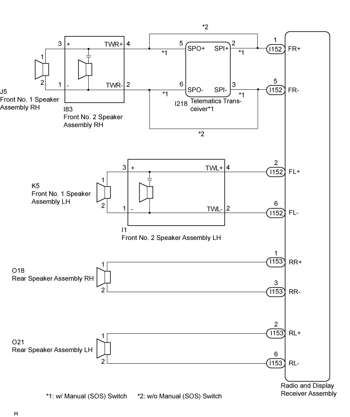
AUDIO AND VISUAL SYSTEM (for Radio and Display Type) > Speaker Circuit |
| 1.CHECK SPEAKER (OPERATION CHECK) |
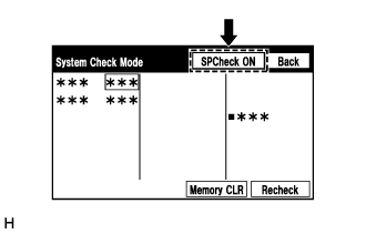 |
Enter the "System Check Mode" screen. Refer to Check Speaker in Operation Check (Click here).
Perform the operation check above and determine the speaker that is not operating.
| Result | Proceed to |
| Front No. 1 speaker assembly or front No. 2 speaker assembly (w/o Manual (SOS) Switch) | A |
| Front No. 1 speaker assembly or front No. 2 speaker assembly (w/ Manual (SOS) Switch) | B |
| Rear speaker assembly | C |
|
| ||||
|
| ||||
| A | |
 |
| 2.CHECK HARNESS AND CONNECTOR (RADIO AND DISPLAY RECEIVER ASSEMBLY - FRONT SPEAKER) |
Disconnect the I152 radio and display receiver assembly connector.
Disconnect the I83 and I1 front No. 2 speaker assembly connectors.
Disconnect the J5 and K5 front No. 1 speaker assembly connectors.
Measure the resistance according to the value(s) in the table below.
| Tester Connection | Condition | Specified Condition |
| I152-1 (FR+) - I83-4 (TWR+) | Always | Below 1 Ω |
| I152-5 (FR-) - I83-2 (TWR-) | Always | Below 1 Ω |
| I152-2 (FL+) - I1-4 (TWL+) | Always | Below 1 Ω |
| I152-6 (FL-) - I1-2 (TWL-) | Always | Below 1 Ω |
| I83-3 (+) - J5-1 | Always | Below 1 Ω |
| I83-1 (-) - J5-2 | Always | Below 1 Ω |
| I1-3 (+) - K5-1 | Always | Below 1 Ω |
| I1-1 (-) - K5-2 | Always | Below 1 Ω |
| I152-1 (FR+) or I83-4 (TWR+) - Body ground | Always | 10 kΩ or higher |
| I152-5 (FR-) or I83-2 (TWR-) - Body ground | Always | 10 kΩ or higher |
| I152-2 (FL+) or I1-4 (TWL+) - Body ground | Always | 10 kΩ or higher |
| I152-6 (FL-) or I1-2 (TWL-) - Body ground | Always | 10 kΩ or higher |
| I83-3 (+) or J5-1 - Body ground | Always | 10 kΩ or higher |
| I83-1 (-) or J5-2 - Body ground | Always | 10 kΩ or higher |
| I1-3 (+) or K5-1 - Body ground | Always | 10 kΩ or higher |
| I1-1 (-) or K5-2 - Body ground | Always | 10 kΩ or higher |
| Result | Proceed to |
| NG | A |
| OK | B |
|
| ||||
| A | ||
 | ||
| ||
| 3.CHECK HARNESS AND CONNECTOR (RADIO AND DISPLAY RECEIVER ASSEMBLY - TELEMATICS TRANSCEIVER - FRONT SPEAKER) |
Disconnect the I152 radio and display receiver assembly connector.
Disconnect the I83 and I1 front No. 2 speaker assembly connectors.
Disconnect the I218 telematics transceiver connector.
Disconnect the J5 and K5 front No. 1 speaker assembly connectors.
Measure the resistance according to the value(s) in the table below.
| Tester Connection | Condition | Specified Condition |
| I152-1 (FR+) - I218-2 (SPI+) | Always | Below 1 Ω |
| I218-5 (SPO+) - I83-4 (TWR+) | Always | Below 1 Ω |
| I152-5 (FR-) - I218-3 (SPI-) | Always | Below 1 Ω |
| I218-6 (SPO-) - I83-2 (TWR-) | Always | Below 1 Ω |
| I152-2 (FL+) - I1-4 (TWL+) | Always | Below 1 Ω |
| I152-6 (FL-) - I1-2 (TWL-) | Always | Below 1 Ω |
| I83-3 (+) - J5-1 | Always | Below 1 Ω |
| I83-1 (-) - J5-2 | Always | Below 1 Ω |
| I1-3 (+) - K5-1 | Always | Below 1 Ω |
| I1-1 (-) - K5-2 | Always | Below 1 Ω |
| I152-1 (FR+) or I218-2 (SPI+) - Body ground | Always | 10 kΩ or higher |
| I218-5 (SPO+) or I83-4 (TWR+) - Body ground | Always | 10 kΩ or higher |
| I152-5 (FR-) or I218-3 (SPI-) - Body ground | Always | 10 kΩ or higher |
| I218-6 (SPO-) or I83-2 (TWR-) - Body ground | Always | 10 kΩ or higher |
| I152-2 (FL+) or I1-4 (TWL+) - Body ground | Always | 10 kΩ or higher |
| I152-6 (FL-) or I1-2 (TWL-) - Body ground | Always | 10 kΩ or higher |
| I83-3 (+) or J5-1 - Body ground | Always | 10 kΩ or higher |
| I83-1 (-) or J5-2 - Body ground | Always | 10 kΩ or higher |
| I1-3 (+) or K5-1 - Body ground | Always | 10 kΩ or higher |
| I1-1 (-) or K5-2 - Body ground | Always | 10 kΩ or higher |
|
| ||||
| OK | |
|
| 4.INSPECT TELEMATICS TRANSCEIVER |
Remove the telematics transceiver Click here.
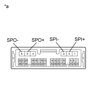 |
Measure the resistance according to the value(s) in the table below.
| Tester Connection | Condition | Specified Condition |
| 2 (SPI+) - 5 (SPO+) | Always | Below 1 Ω |
| 3 (SPI-) - 6 (SPO-) | Always | Below 1 Ω |
| 2 (SPI+) - 3 (SPI-) | Always | 10 kΩ or higher |
| 5 (SPO+) - 6 (SPO-) | Always | 10 kΩ or higher |
| 2 (SPI+) or 5 (SPO+) - Body ground | Always | 10 kΩ or higher |
| 3 (SPI-) or 6 (SPO-) - Body ground | Always | 10 kΩ or higher |
| *a | Component without harness connected (Telematics Transceiver) |
|
| ||||
| OK | |
|
| 5.INSPECT FRONT NO. 2 SPEAKER ASSEMBLY |
Remove the front No. 2 speaker assembly.
for TMMK Made: Click here
for TMC, TMMR Made: Click here
Inspect the front No. 2 speaker assembly.
for TMMK Made: Click here
for TMC, TMMR Made: Click here
|
| ||||
| OK | ||
| ||
| ||
| 6.INSPECT FRONT NO. 1 SPEAKER ASSEMBLY |
Remove the front No. 1 speaker assembly.
for TMMK Made: Click here
for TMC, TMMR Made: Click here
Inspect the front No. 1 speaker assembly.
for TMMK Made: Click here
for TMC, TMMR Made: Click here
|
| ||||
| OK | ||
| ||
| ||
| 7.CHECK HARNESS AND CONNECTOR (RADIO AND DISPLAY RECEIVER ASSEMBLY - REAR SPEAKER ASSEMBLY) |
Disconnect the I153 radio and display receiver assembly connector.
Disconnect the O18 and O21 rear speaker assembly connectors.
Measure the resistance according to the value(s) in the table below.
| Tester Connection | Condition | Specified Condition |
| I153-1 (RR+) - O18-1 | Always | Below 1 Ω |
| I153-3 (RR-) - O18-2 | Always | Below 1 Ω |
| I153-2 (RL+) - O21-1 | Always | Below 1 Ω |
| I153-6 (RL-) - O21-2 | Always | Below 1 Ω |
| I153-1 (RR+) or O18-1 - Body ground | Always | 10 kΩ or higher |
| I153-3 (RR-) or O18-2 - Body ground | Always | 10 kΩ or higher |
| I153-2 (RL+) or O21-1 - Body ground | Always | 10 kΩ or higher |
| I153-6 (RL-) or O21-2 - Body ground | Always | 10 kΩ or higher |
|
| ||||
| OK | |
|
| 8.INSPECT REAR SPEAKER ASSEMBLY |
Remove the rear speaker assembly.
for TMMK Made: Click here
for TMC, TMMR Made: Click here
Inspect the rear speaker assembly.
for TMMK Made: Click here
for TMC, TMMR Made: Click here
|
| ||||
| OK | ||
| ||
| ||

