DTC P071512 Input/Turbine Speed Sensor "A" Circuit Short to Battery |
DTC P071514 Input/Turbine Speed Sensor "A" Circuit Short to Ground or Open |
DTC P071531 Input/Turbine Speed Sensor "A" No Signal |
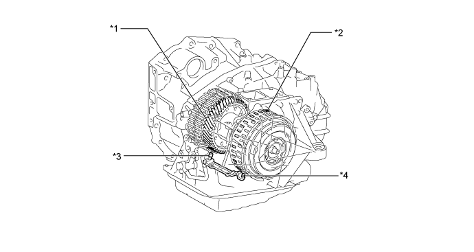
| *1 | Counter Gear | *2 | Clutch Drum |
| *3 | Output Speed Sensor NC | *4 | Input Speed Sensor NT |
| DTC No. | DTC Detection Condition | Trouble Area |
| P071512 | 1. Diagnosis Condition 2. Malfunction Status 3. Malfunction Time 4. Other
|
|
| P071514 | 1. Diagnosis Condition 2. Malfunction Status 3. Malfunction Time 4. Other
|
|
| P071531 | 1. Diagnosis Condition 2. Malfunction Status 3. Malfunction Time 4. Other
|
|
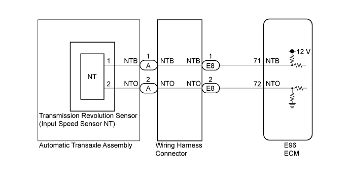
| DATA LIST |
Warm up the engine.
Turn the engine switch off.
Connect the GTS to the DLC3.
Turn the engine switch on (IG).
Turn the GTS on.
Enter the following menus: Powertrain / Transmission / Data List.
Read the Data List according to the display on the GTS.
| Tester Display | Measurement Item/Range | Normal Condition | Diagnostic Note |
| NT Sensor Speed | Input turbine speed/ Min.: 0 rpm Max.: 12750 rpm |
| Data is displayed in increments of 50 rpm |
| 1.INSPECT TRANSMISSION REVOLUTION SENSOR (SPEED SENSOR INSTALLATION) |
Remove the transmission valve body assembly.
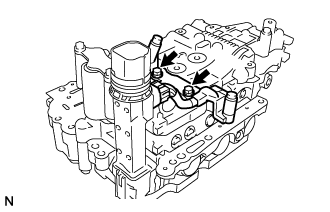 |
Make sure that the connector is properly connected, and check the transmission revolution sensor installation (Click here).
|
| ||||
| OK | |
 |
| 2.INSPECT TRANSMISSION WIRE |
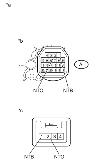 |
Disconnect the transmission revolution sensor connector.
| *a | Component without harness connected (Transmission Wire) |
| *b | Wiring harness connector side |
| *c | Transmission revolution sensor side |
Measure the resistance according to the value(s) in the table below.
| Tester Connection | Condition | Specified Condition |
| 1 (NTB) sensor side - A-1 (NTB) wiring harness connector side | Always | Below 1 Ω |
| 2 (NTO) sensor side - A-2 (NTO) wiring harness connector side | Always | Below 1 Ω |
| 1 (NTB) sensor side - Body ground and other terminals | Always | 10 kΩ or higher |
| 2 (NTO) sensor side - Body ground and other terminals | Always | 10 kΩ or higher |
|
| ||||
| OK | |
|
| 3.CHECK HARNESS AND CONNECTOR (ECM - WIRING HARNESS CONNECTOR) |
Disconnect the E96 ECM connector.
Measure the resistance according to the value(s) in the table below.
| Tester Connection | Condition | Specified Condition |
| E8-1 (NTB) - E96-71 (NTB) | Always | Below 1 Ω |
| E8-2 (NTO) - E96-72 (NTO) | Always | Below 1 Ω |
| E8-1 (NTB) or E96-71 (NTB) - Body ground and other terminals | Always | 10 kΩ or higher |
| E8-2 (NTO) or E96-72 (NTO) - Body ground and other terminals | Always | 10 kΩ or higher |
|
| ||||
| OK | |
|
| 4.INSPECT WIRING HARNESS CONNECTOR |
Remove the wiring harness connector.
Measure the resistance according to the value(s) in the table below.
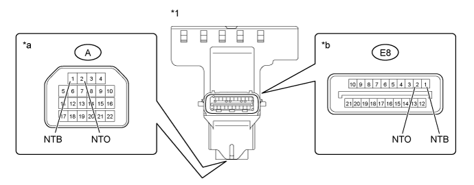
| *1 | Wiring Harness Connector | - | - |
| *a | Transmission wire side | *b | ECM side |
| Tester Connection | Condition | Specified Condition |
| E8-1 (NTB) - A-1 (NTB) | Always | Below 1 Ω |
| E8-2 (NTO) - A-2 (NTO) | Always | Below 1 Ω |
| E8-1 (NTB) - All other terminals | Always | 10 kΩ or higher |
| E8-2 (NTO) - All other terminals | Always | 10 kΩ or higher |
|
| ||||
| OK | |
|
| 5.REPLACE TRANSMISSION REVOLUTION SENSOR |
Replace the transmission revolution sensor (Click here).
| NEXT | |
|
| 6.CHECK IF DTC OUTPUT RECURS (DTC P071512, P071514 AND/OR P071531) |
Connect the GTS to the DLC3.
Start the engine and turn the GTS on.
Clear the DTCs (Click here).
Perform the monitor drive pattern (Click here).
Enter the following menus: Powertrain / Transmission / Trouble Codes.
Read the DTCs using the GTS.
| Result | Proceed to |
| DTC P071512, P071514 and/or P071531 is output | A |
| DTCs are not output | B |
|
| ||||
| A | ||
 | ||
| ||
