| B |  |
| Go to step 6 |
DTC P033525 Crankshaft Position Sensor "A" Signal Shape/Waveform Failure |
DTC P03353A Crankshaft Position Sensor "A" Signal has Too Many Pulses |
DTC P033564 Crankshaft Position Sensor "A" Signal Plausibility Failure |
| DTC No. | DTC Detection Condition | Trouble Area |
| P033525 | The pulse width of the crankshaft position sensor exceeding the threshold is detected during engine speed of 1800 rpm or higher (1 trip detection logic). |
|
| P03353A | An engine reverse signal is detected during engine cranking or normally rotating at 1800 rpm or higher (1 trip detection logic). |
|
| P033564 | The input signal voltage of the crankshaft position sensor continues at 5 V for 4 seconds during engine rotation (1 trip detection logic). |
|
| Required Sensors/Components (Main) | Crankshaft position sensor |
| Required Sensors/Components (Related) | Camshaft position sensor |
| Frequency of Operation | Continuous |
| GTS Display | Description |
| NORMAL |
|
| ABNORMAL |
|
| INCOMPLETE |
|
| N/A |
|
| 1.CHECK ANY OTHER DTCS OUTPUT (IN ADDITION TO DTC P033525, P03353A AND/OR P033564) |
Connect the GTS to the DLC3.
Turn the engine switch on (IG).
Turn the GTS on.
Enter the following menus: Powertrain / Engine / Trouble Codes.
Read the DTCs.
| Result | Proceed to |
| DTC P033525, P03353A or P033564 and P033515 are output | A |
| DTC P033525, P03353A and/or P033564 is output | B |
|
| ||||
| A | |
 |
| 2.CHECK TERMINAL VOLTAGE (POWER SOURCE OF CRANKSHAFT POSITION SENSOR) |
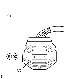 |
Disconnect the crankshaft position sensor connector.
| *a | Front view of wire harness connector (to Crankshaft Position Sensor) |
Turn the engine switch on (IG).
Measure the voltage according to the value(s) in the table below.
| Tester Connection | Condition | Specified Condition |
| E100-1 (VC) - Body ground | Engine switch on (IG) | 4.5 to 5.5 V |
|
| ||||
| OK | |
|
| 3.CHECK HARNESS AND CONNECTOR (CRANKSHAFT POSITION SENSOR - ECM) |
Disconnect the crankshaft position sensor connector.
Disconnect the ECM connector.
Measure the resistance according to the value(s) in the table below.
| Tester Connection | Condition | Specified Condition |
| E100-3 (NE+) - E96-76 (NE+) | Always | Below 1 Ω |
| E100-2 (NE-) - E96-109 (NE-) | Always | Below 1 Ω |
| E100-3 (NE+) or E96-76 (NE+) - Body ground and other terminals | Always | 10 kΩ or higher |
| E100-2 (NE-) or E96-109 (NE-) - Body ground and other terminals | Always | 10 kΩ or higher |
|
| ||||
| OK | |
|
| 4.CHECK SENSOR INSTALLATION (CRANKSHAFT POSITION SENSOR) |
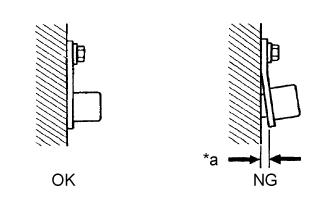 |
Check the crankshaft position sensor installation condition.
| *a | Clearance |
|
| ||||
| OK | |
|
| 5.INSPECT CRANKSHAFT (TEETH OF CRANKSHAFT POSITION SENSOR PLATE) |
Inspect the teeth of the crankshaft position sensor plate.
|
| ||||
| OK | |
|
| 6.REPLACE CRANKSHAFT POSITION SENSOR |
Replace the crankshaft position sensor (Click here).
| NEXT | |
|
| 7.CHECK WHETHER DTC OUTPUT RECURS (DTC P033525, P03353A AND/OR P033564) |
Connect the GTS to the DLC3.
Turn the engine switch on (IG).
Turn the GTS on.
Clear the DTCs.
Turn the engine switch off and wait for at least 30 seconds.
Turn the engine switch on (IG).
Turn the GTS on.
Start the engine.
Drive the vehicle in accordance with the driving pattern described in Confirmation Driving Pattern.
Enter the following menus: Powertrain / Engine / Trouble Codes.
Read the DTCs.
| Result | Proceed to |
| DTCs are not output | A |
| DTC P033525, P03353A or P033564 is output | B |
|
| ||||
| A | ||
 | ||
| ||
| 8.CHECK HARNESS AND CONNECTOR (CRANKSHAFT POSITION SENSOR - ECM) |
Disconnect the crankshaft position sensor connector.
Disconnect the ECM connector.
Measure the resistance according to the value(s) in the table below.
| Tester Connection | Condition | Specified Condition |
| E100-1 (VC) - E96-110 (VCNE) | Always | Below 1 Ω |
| E100-1 (VC) or E96-110 (VCNE) - Body ground and other terminals | Always | 10 kΩ or higher |
|
| ||||
| OK | ||
| ||
| ||
