
SFI SYSTEM > Rough Idling |
| Problem Symptom | Suspected Area | Trouble Area | |
|
| Ignition system |
|
| Fuel system |
| ||
| Intake and exhaust systems |
| ||
| Other control systems |
| ||
| Engine |
| ||
| High load from another system |
| ||
| SYMPTOM AND CAUSE OF SYSTEM MALFUNCTION |
Ignition system
| Main cause of malfunction | Performance degradation (wear, existence of foreign matter, etc.) |
| Symptom | Engine speed fluctuation due to abnormal combustion |
| Data List | Misfire Count Cylinder #1 to #4 |
| |
| Main cause of malfunction | Internal malfunction |
| Problem symptom | Engine speed fluctuation due to abnormal combustion |
| Data List | Misfire Count Cylinder #1 to #4 |
Fuel system
| Main cause of malfunction | Blockage |
| Problem symptom |
|
| Data List |
|
| |
|
| Main cause of malfunction |
|
| Problem symptom |
|
Intake and exhaust systems
| Main cause of malfunction | Improper operation, sticking |
| Problem symptom |
|
| Data List |
|
| Main cause of malfunction | Performance degradation (existence of foreign matter, etc.) |
| Problem symptom | Lack of power |
| Data List | Mass Air Flow Sensor |
| |
| Main cause of malfunction | Inappropriate trim volume adjustment due to accumulation of deposits |
| Problem symptom |
|
| Data List |
|
| Main cause of malfunction | Deviation in sensor characteristics |
| Problem symptom | Abnormal combustion due to deviation of actual air fuel ratio from calculated ratio |
| Data List |
|
Engine
| Main cause of malfunction |
|
| Problem symptom |
|
| Data List |
|
| |
| Data List Items Related to Rough Idling |
| 1.INTERVIEW THE CUSTOMER |
Interview the customer for details about the conditions when the rough idle occurred.
| Problem Symptom | Suspected Area |
| Engine idles roughly after cold start but runs smoothly when the engine speed is increased | Excessive EGR flow due to close malfunction of the EGR valve |
| Hesitation or lack of power occurs during acceleration, regardless of whether engine is cold or warm |
|
| Engine stalls or is difficult to start immediately after engine stalled, regardless of whether engine is cold or warm | Deposits in intake system or combustion chamber caught temporarily on intake or exhaust valve |
| Temporary deviation in the electrical throttle system idle speed control due to external factors (fuel quality, air conditioning system (environmental causes or low refrigerant pressure) or charging system (battery deterioration or low power generation by the alternator)) |
| NEXT | |
|
| 2.CHECK DTC OUTPUT |
Connect the GTS to the DLC3.
Turn the engine switch on (IG).
Turn the GTS on.
Perform a road test.
Enter the following menus: Powertrain / Engine / Trouble Codes.
Read the DTCs.
| Result | Proceed to |
| DTCs are not output | A |
| DTC is output (DTCs other than P160300, P160400 or P160500 are output) | B |
|
| ||||
| A | |
|
| 3.SYMPTOM CONFIRMATION |
Check if the problem symptoms reported in the customer problem analysis recur.
| Result | Proceed to |
| The problem symptom recurs | A |
| The problem symptom does not recur (occurred in the past) | B |
|
| ||||
| A | |
|
| 4.READ VALUE USING GTS (ISC F/B LEARN TORQUE) |
Connect the GTS to the DLC3.
Turn the engine switch on (IG).
Turn the GTS on.
Enter the following menus: Powertrain / Engine / Data List / All Data / ISC F/B Learn Torque.
Read the value displayed on the GTS.
| Result | Proceed to |
| Less than 15 Nm | A |
| Other than above | B |
|
| ||||
| A | |
|
| 5.READ VALUE USING GTS (SHORT FT BANK 1 AND LONG FT BANK 1) |
Connect the GTS to the DLC3.
Turn the engine switch on (IG).
Turn the GTS on.
Enter the following menus: Powertrain / Engine / Data List / All Data / Short FT Bank 1 and Long FT Bank 1.
Read the value displayed on the GTS.
| Data List | Result | Proceed to |
| Short FT Bank 1 + Long FT Bank 1 | -15% or higher, or less than 15% | A |
| Other than above | B |
|
| ||||
| A | |
|
| 6.PERFORM ACTIVE TEST USING GTS (D-4S (FUEL CUT)) |
Connect the GTS to the DLC3.
Turn the engine switch on (IG).
Turn the GTS on.
Start the engine
Enter the following menus: Powertrain / Engine / Active Test / D-4S (Fuel Cut) / Data List / All Data / Engine Speed.
According to the display on the GTS, perform the Active Test and check for a malfunctioning cylinder.
| Result | Proceed to |
| One cylinder is malfunctioning | A |
| Multiple or all cylinders are malfunctioning, or the malfunctioning cylinder cannot be determined. | B |
|
| ||||
| A | |
|
| 7.PERFORM ACTIVE TEST USING GTS (CHECK THE CYLINDER COMPRESSION) |
Warm up the engine.
Turn the engine switch off.
Connect the GTS to the DLC3.
Turn the engine switch on (IG).
Turn the GTS on.
Enter the following menus: Powertrain / Engine / Active Test / Check the Cylinder Compression / Data List / Compression / Engine Speed Cylinder #1 to #4 and Average Engine Speed of All Cylinder.
While the engine is not running, press the Active Test button to change Check the Cylinder Compression to "Start".
Crank the engine for about 10 seconds.
Monitor the engine speed (Engine Speed Cylinder #1 to #4 and Average Engine Speed of All Cylinder) displayed on the GTS.
Stop cranking the engine, and then change "Check the Cylinder Compression" to "Stop" after the engine stops.
Read the value.
| Result | Proceed to |
| There is no variation in "Engine Speed Cylinder #1 to #4" (All cylinders display approximately the same value for "Engine Speed Cylinder #1 to #4") | A |
| There is variation in "Engine Speed Cylinder #1 to #4" (Only one cylinder displays a value for "Engine Speed Cylinder #1 to #4" that differs considerably) | B |
|
| ||||
| A | |
|
| 8.PERFORM ACTIVE TEST USING GTS (D-4S (INJECTION VOLUME)) |
Connect the GTS to the DLC3.
Turn the engine switch on (IG).
Turn the GTS on.
Start the engine and warm it up until the engine coolant temperature 75°C (167°F) or higher with all the accessories switched off.
Idle the engine.
Enter the following menus: Powertrain / Engine / Active Test / D-4S (Injection Volume).
According to the display on the GTS, perform the Active Test and check the vehicle conditions when increasing and decreasing the fuel injection volume.
| Result | Proceed to |
| Malfunction is still present even if the fuel injection volume is changed | A |
| Malfunction disappears when the fuel injection volume is changed | B |
|
| ||||
| A | |
|
| 9.CHECK IGNITION SYSTEM |
Check the ignition system.
| Result | Proceed to |
| The malfunctioning cylinder does not return to normal | A |
| The malfunctioning cylinder returned to normal | B |
|
| ||||
| A | |
|
| 10.INSPECT OTHER RELATED COMPONENTS |
Check the ignition coil assembly power source circuit, wire harness and connectors.
|
| ||||
| 11.REMOVE FOREIGN MATTER (CLEAN THROTTLE BODY WITH MOTOR ASSEMBLY) |
Clean off any deposits from the inside of the throttle body with motor assembly.
Push open the throttle valve and wipe off any carbon from the valve and bore using a piece of cloth soaked in non-residue solvent.
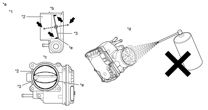
| *1 | Throttle Body with Motor Assembly | *2 | Bore |
| *3 | Valve | - | - |
| *a | Reference | *b | Throttle Body with Motor Assembly Cross-section Diagram |
| *c | When valve fully opened | *d | Do not directly apply cleaner |
| *e | Deposits | - | - |
| NEXT | |
|
| 12.PERFORM CONFIRMATION DRIVING PATTERN |
Perform "Inspection After Repair" after cleaning the throttle body with motor assembly (Click here).
Connect the GTS to the DLC3.
Turn the engine switch on (IG).
Turn the GTS on.
Start the engine and warm it up until the engine coolant temperature reaches 75°C (167°F) or higher.
Allow the engine to idle for 3 minutes or more and confirm that the engine speed is within the specified range.
|
| ||||
| 13.CHECK CYLINDER COMPRESSION PRESSURE |
Measure the cylinder compression pressure. If the compression pressure of a cylinder is low, inspect the engine assembly and repair or replace parts as necessary .
|
| ||||
| 14.REPLACE FUEL INJECTOR ASSEMBLY |
Replace the fuel injector assembly of the malfunctioning cylinder.
|
| ||||
| 15.PERFORM ACTIVE TEST USING GTS (CONTROL THE EGR STEP POSITION) |
Connect the GTS to the DLC3.
Turn the engine switch on (IG).
Turn the GTS on.
Start the engine and warm it up until the engine coolant temperature reaches 75°C (167°F) or higher.
Enter the following menus: Powertrain / Engine / Active Test / Control the EGR Step Position / Data List / All Data / Engine Speed.
Perform the Active Test and check the vehicle condition when operating the EGR valve assembly.
| Result | Proceed to |
| Vehicle condition changes during the Active Test (Malfunction occurs when the EGR valve is open and disappears when the EGR valve is closed) | A |
| Vehicle condition does not change during the Active Test (Malfunction occurs whether the EGR valve is open or closed) | B |
|
| ||||
| A | |
|
| 16.READ VALUE USING GTS (MASS AIR FLOW SENSOR) |
Connect the GTS to the DLC3.
Turn the engine switch on (IG).
Turn the GTS on.
Start the engine and warm it up until the engine coolant temperature 75°C (167°F) or higher with all the accessories switched off.
Enter the following menus: Powertrain / Engine / Data List / All Data / Mass Air Flow Sensor.
According to the display on the GTS, read the Data List when the engine is running.
| Result | Proceed to |
| Idling (warmed up engine, without load): 1.0 to 4.0 gm/sec Engine speed 2000 rpm (warmed up engine, without load): 4.1 to 8.1 gm/sec Engine speed 3000 rpm (warmed up engine, without load): 6.2 to 11.2 gm/sec | A |
| Other than above | B |
|
| ||||
| A | |
|
| 17.PERFORM ACTIVE TEST USING GTS (D-4S (INJECTION VOLUME)) |
Connect the GTS to the DLC3.
Turn the engine switch on (IG).
Turn the GTS on.
Start the engine and warm it up until the engine coolant temperature 75°C (167°F) or higher with all the accessories switched off.
Warm up the air fuel ratio sensor at an engine speed of 2500 rpm for 90 seconds.
Idle the engine.
Enter the following menus: Powertrain / Engine / Active Test / D-4S (Injection Volume) / Data List / All Data / A/F (O2) Sensor Voltage B1S1 and O2 Sensor Voltage B1S2.
According to the display on the GTS, perform the Active Test and check the vehicle conditions when increasing and decreasing the fuel injection volume.
| GTS Display (Sensor) | Injection Volume | Voltage |
| A/F (O2) Sensor Voltage B1S1 (Air fuel ratio) | 12% | Below 3.1 V |
| -12% | Higher than 3.4 V | |
| O2 Sensor Voltage B1S2 (Heated oxygen) | 12% | Higher than 0.55 V |
| -12% | Below 0.4 V |
| Result | Proceed to |
| Output voltage values are abnormal | A |
| Malfunction disappears when fuel injection volume is increased | B |
| Malfunction is still present when fuel injection volume is increased, even if output voltage values are normal | C |
|
| ||||
|
| ||||
| A | |
|
| 18.REPLACE AIR FUEL RATIO SENSOR AND HEATED OXYGEN SENSOR |
Replace the air fuel ratio sensor (Click here).
Replace the heated oxygen sensor (Click here).
|
| ||||
| 19.REPLACE EGR VALVE ASSEMBLY |
Replace the EGR valve assembly (Click here).
|
| ||||
| 20.REPLACE FUEL INJECTOR ASSEMBLY |
Replace the fuel injector assemblies of all cylinders.
|
| ||||
| 21.CHECK INTAKE SYSTEM |
Check for air leaks or blockage in the intake system components. If a connection problem or foreign matter is found, repair the connection or remove the foreign matter.
|
| ||||
| 22.INSPECT OTHER RELATED COMPONENTS |
Inspect other related components.
| NEXT | |
|
| 23.REPAIR OR REPLACE MALFUNCTIONING PARTS |
Repair or replace the malfunctioning part.
Perform "Inspection After Repair" after repairing or replacing the malfunctioning part (Click here).
| NEXT | |
|
| 24.CONDUCT CONFIRMATION TEST |
Check that the idle has returned to normal.
| NEXT | ||
 | ||
| ||

