NETWORKING NETWORK GATEWAY ECU REMOVAL
CAUTION / NOTICE / HINT
The necessary procedures (adjustment, calibration, initialization, or registration) that must be performed after parts are removed and installed, or replaced during central gateway ECU (network gateway ECU) removal/installation are shown below.
| Replaced Part or Performed Procedure | Necessary Procedure | Effect/Inoperative Function when Necessary Procedure not Performed | Link |
|---|---|---|---|
| Battery terminal is disconnected/reconnected | Perform steering sensor zero point calibration | Lane Tracing Assist System | ( ) |
| Pre-collision system | |||
| Memorize steering angle neutral point | Parking assist monitor system | ()
|
|
| Panoramic View Monitor System | ()
|
||
w/o Parking Support Brake System:
Clearance warning ECU assembly |
Register bumper type | TOYOTA parking assist-sensor system | ()
|
w/ Parking Support Brake System:
Clearance warning ECU assembly |
·
Measure ultrasonic sensor detection angle ·
Register bumper type ·
Register ultrasonic sensor detection angle |
·
TOYOTA Parking Assist-sensor System ·
Parking Support Brake System |
()
|
- CAUTION:
-
-
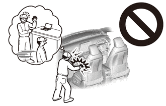
Some of these service operations affect the SRS airbag system. Read the precautionary notices concerning the SRS airbag system before servicing.
-
Click hereVehicle Interior>SUPPLEMENTAL RESTRAINT SYSTEMS>AIRBAG SYSTEM>PRECAUTION
PROCEDURE

 1. PRECAUTION
- NOTICE:
-
After turning the ignition switch off, waiting time may be required before disconnecting the cable from the negative (-) battery terminal. Therefore, make sure to read the disconnecting the cable from the negative (-) battery terminal notices before proceeding with work.
-
Click hereGeneral>INTRODUCTION>REPAIR INSTRUCTION>PRECAUTION
2.DISCONNECT CABLE FROM NEGATIVE BATTERY TERMINAL
for M20A-FKS:
Click hereGeneral>MAINTENANCE>M20A-FKS BATTERY>REMOVAL
for A25A-FKS:
Click hereGeneral>MAINTENANCE>A25A-FKS BATTERY>REMOVAL
for 2GR-FKS:
Click hereGeneral>MAINTENANCE>2GR-FKS BATTERY>REMOVAL
- CAUTION:
-
- ·
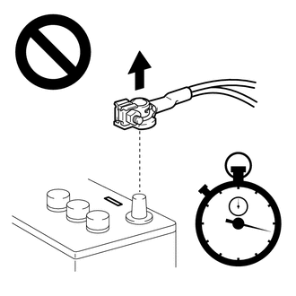
Wait at least 90 seconds after disconnecting the cable from the negative (-) battery terminal to disable the SRS system.
·If an airbag deploys for any reason, it may cause a serious injury.
55435B
3.REMOVE NO. 1 METER HOOD CLUSTER (for LHD)
55012A
4.REMOVE NO. 2 INSTRUMENT PANEL GARNISH SUB-ASSEMBLY (for LHD)
55476C
5.REMOVE INSTRUMENT PANEL FINISH PLATE GARNISH (for LHD)
67913
6.REMOVE FRONT DOOR SCUFF PLATE RH (for LHD)
- HINT:
-
Use the same procedure as for the LH side.
-
Click hereVehicle Interior>INTERIOR PANELS / TRIM>ROOF HEADLINING>REMOVAL
62111A
7.REMOVE COWL SIDE TRIM SUB-ASSEMBLY RH (for LHD)
- HINT:
-
Use the same procedure as for the LH side.
-
Click hereVehicle Interior>INTERIOR PANELS / TRIM>ROOF HEADLINING>REMOVAL
62311B
8.DISCONNECT FRONT DOOR OPENING TRIM WEATHERSTRIP RH (for LHD)
55317A
9.REMOVE INSTRUMENT SIDE PANEL RH (for LHD)
55607
10.REMOVE NO. 2 INSTRUMENT PANEL UNDER COVER SUB-ASSEMBLY (for LHD)
73990
11.REMOVE LOWER NO. 2 INSTRUMENT PANEL AIRBAG ASSEMBLY (for LHD, w/ Passenger Side Knee Airbag)
55303B
12.REMOVE LOWER INSTRUMENT PANEL SUB-ASSEMBLY (for LHD, w/o Passenger Side Knee Airbag)
55303B
13.REMOVE LOWER INSTRUMENT PANEL SUB-ASSEMBLY (for LHD, w/ Passenger Side Knee Airbag)
82877
14.REMOVE ECU INTEGRATION BOX RH (for LHD, w/ ECU Integration Box RH)
Disconnect each connector.
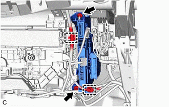
Disengage the 2 clamps.
Remove the bolt, nut and ECU integration box RH.
89111
15.REMOVE CENTRAL GATEWAY ECU (NETWORK GATEWAY ECU) (for LHD, w/o ECU Integration Box RH)
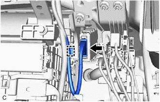
Disconnect the central gateway ECU (network gateway ECU) connector.
Disengage the clamp.
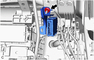
Remove the nut and central gateway ECU (network gateway ECU).
89111
16.REMOVE CENTRAL GATEWAY ECU (NETWORK GATEWAY ECU) (for LHD, w/ ECU Integration Box RH)
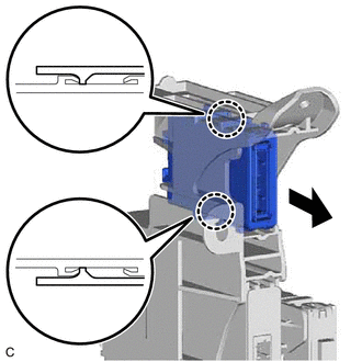
Disengage the 2 claws and remove the central gateway ECU (network gateway ECU).
- NOTICE:
- ·
If the ECU integration box is deformed or damaged, replace it.
·Do not bend the 2 claws more than necessary.
55435B
17.REMOVE NO. 1 METER HOOD CLUSTER (for RHD)
- HINT:
-
Use the same procedure as for LHD.
-
Click hereVehicle Interior>INTERIOR PANELS / TRIM>FRONT CONSOLE BOX>REMOVAL
55434B
18.REMOVE LOWER CENTER INSTRUMENT PANEL FINISH PANEL (for RHD)
- HINT:
-
Use the same procedure as for LHD.
-
Click hereVehicle Interior>INTERIOR PANELS / TRIM>FRONT CONSOLE BOX>REMOVAL
67913
19.REMOVE FRONT DOOR SCUFF PLATE RH (for RHD)
- HINT:
-
Use the same procedure as for the LH side.
-
Click hereVehicle Interior>INTERIOR PANELS / TRIM>ROOF HEADLINING>REMOVAL
62111A
20.REMOVE COWL SIDE TRIM SUB-ASSEMBLY RH (for RHD)
- HINT:
-
Use the same procedure as for the LH side.
-
Click hereVehicle Interior>INTERIOR PANELS / TRIM>ROOF HEADLINING>REMOVAL
62311B
21.DISCONNECT FRONT DOOR OPENING TRIM WEATHERSTRIP RH (for RHD)
55317A
22.REMOVE INSTRUMENT SIDE PANEL RH (for RHD)
- HINT:
-
Use the same procedure as for the LH side.
-
Click hereVehicle Interior>INTERIOR PANELS / TRIM>INSTRUMENT PANEL SAFETY PAD>REMOVAL
55606
23.REMOVE NO. 1 INSTRUMENT PANEL UNDER COVER SUB-ASSEMBLY (for RHD)
55436B
24.REMOVE NO. 2 METER HOOD CLUSTER (for RHD)
- HINT:
-
Use the same procedure as for LHD.
-
Click hereVehicle Interior>INTERIOR PANELS / TRIM>INSTRUMENT PANEL SAFETY PAD>REMOVAL
53601
25.REMOVE HOOD LOCK CONTROL LEVER SUB-ASSEMBLY (for RHD)
- HINT:
-
Use the same procedure as for LHD.
-
Click hereVehicle Interior>INTERIOR PANELS / TRIM>INSTRUMENT PANEL SAFETY PAD>REMOVAL
55302D
26.REMOVE NO. 1 INSTRUMENT PANEL SUB-ASSEMBLY (for RHD, w/o Driver Side Knee Airbag)
- HINT:
-
Use the same procedure as for LHD.
-
Click hereVehicle Interior>INTERIOR PANELS / TRIM>INSTRUMENT PANEL SAFETY PAD>REMOVAL
55302D
27.REMOVE NO. 1 INSTRUMENT PANEL SUB-ASSEMBLY (for RHD, w/ Driver Side Knee Airbag)
- HINT:
-
Use the same procedure as for LHD.
-
Click hereVehicle Interior>INTERIOR PANELS / TRIM>INSTRUMENT PANEL SAFETY PAD>REMOVAL
73900
28.REMOVE LOWER NO. 1 INSTRUMENT PANEL AIRBAG ASSEMBLY (for RHD, w/ Driver Side Knee Airbag)
55308B
29.REMOVE NO. 3 INSTRUMENT PANEL TO COWL BRACE SUB-ASSEMBLY (for RHD)
- HINT:
-
Use the same procedure as for LHD.
-
Click hereVehicle Interior>HEATING / AIR CONDITIONING>AIR CONDITIONING UNIT>REMOVAL
82877
30.REMOVE ECU INTEGRATION BOX RH (for RHD, w/ ECU Integration Box RH)
Disconnect each connector.
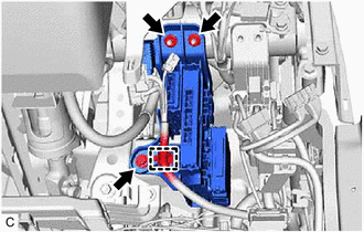
Disengage the clamp.
Remove the bolt, 2 nuts and ECU integration box RH.
89111
31.REMOVE CENTRAL GATEWAY ECU (NETWORK GATEWAY ECU) (for RHD, w/o ECU Integration Box RH)
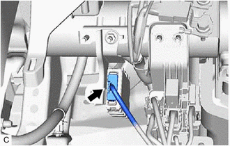
Disconnect the central gateway ECU (network gateway ECU) connector.
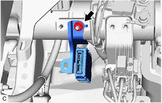
Remove the nut and central gateway ECU (network gateway ECU).
89111
32.REMOVE CENTRAL GATEWAY ECU (NETWORK GATEWAY ECU) (for RHD, w/ ECU Integration Box RH)
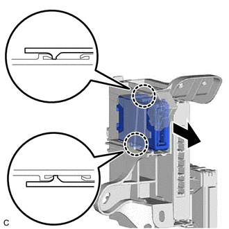
Disengage the 2 claws and remove the central gateway ECU (network gateway ECU).
- NOTICE:
- ·
If the ECU integration box is deformed or damaged, replace it.
·Do not bend the 2 claws more than necessary.