Home › Vehicle Exterior › WIPER / WASHER › WIPER AND WASHER SYSTEM › from 2019.10
RM33C0E _59 Vehicle Exterior _065471 WIPER / WASHER _0332906 WIPER AND WASHER SYSTEM J

WIPER / WASHER  WIPER AND WASHER SYSTEM  Headlight Cleaner Motor and Relay Circuit  


DESCRIPTION

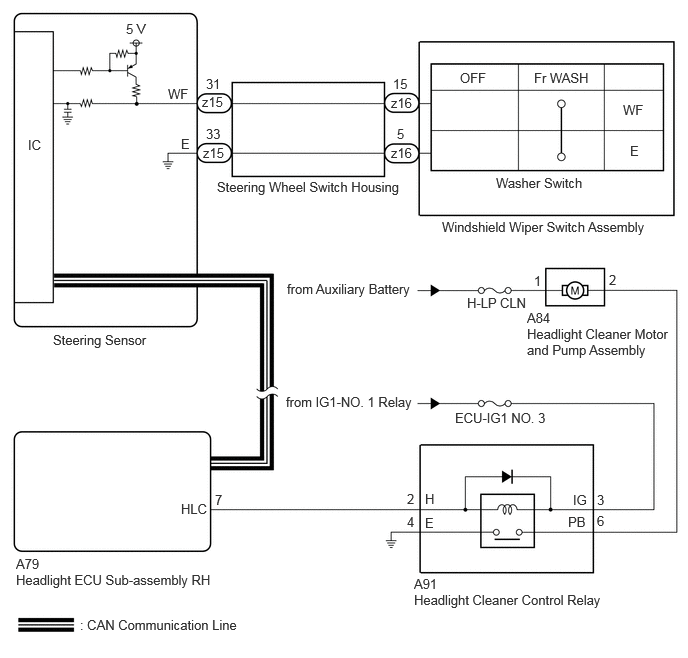
The headlight ECU sub-assembly RH controls the headlight cleaner motor and pump assembly.

WIRING DIAGRAM

for LHD
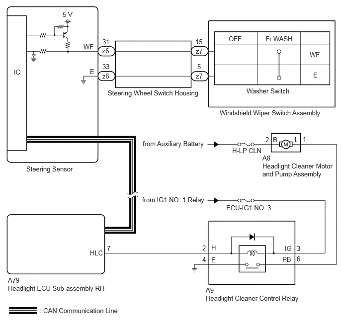

E378698E16
5.5,3.396 6.979,3.802 1.479,0.406 10 false Headlight Cleaner Motor and Pump Assembly 4.74,4.271 6.729,4.469 1.99,0.198 10 false ECU-IG1 NO. 3 2.979,4.104 4.969,4.302 1.99,0.198 10 false from IG1 NO. 1 Relay 5.969,5.125 7.156,5.302 1.188,0.177 10 false IG 5.917,5.354 7.104,5.531 1.188,0.177 10 false PB 4.865,3.073 6.854,3.271 1.99,0.198 10 false H-LP CLN 4.427,5.365 5.615,5.542 1.188,0.177 10 false E 4.427,5.115 5.615,5.292 1.188,0.177 10 false H 4.313,6 5.5,6.177 1.188,0.177 10 false A9 4.313,6.167 6.313,6.458 2,0.292 10 false Headlight Cleaner Control Relay 1.885,5.219 3.073,5.396 1.188,0.177 10 false HLC 0.167,5.792 1.354,5.969 1.188,0.177 10 false A79 0.167,5.958 2.323,6.271 2.156,0.313 10 false Headlight ECU Sub-assembly RH 0.833,6.427 2.99,6.74 2.156,0.313 10 false : CAN Communication Line 2.99,2.927 4.979,3.125 1.99,0.198 10 false from Auxiliary Battery 0.552,3.458 2.542,3.656 1.99,0.198 10 false Steering Sensor 2.24,5.125 3.427,5.302 1.188,0.177 10 false 7 4.24,5.115 5.427,5.292 1.188,0.177 10 false 2 4.24,5.354 5.427,5.531 1.188,0.177 10 false 4 6.219,5.344 7.156,5.51 0.938,0.167 10 false 6 6.219,5.125 7.156,5.292 0.938,0.167 10 false 3 5.5,3.229 6.094,3.469 0.594,0.24 10 false A8 6.177,2.844 6.49,3.01 0.313,0.167 10 false L 5.719,2.844 6.031,3.01 0.313,0.167 10 false B 5.563,2.844 6.75,3.021 1.188,0.177 10 false 2 6.344,2.833 7.146,3.021 0.802,0.188 10 false 1 2.146,1.51 3.333,1.688 1.188,0.177 10 false z6 2.146,0.979 3.333,1.156 1.188,0.177 10 false z6 4.104,0.99 5.292,1.167 1.188,0.177 10 false z7 4.104,1.51 5.292,1.688 1.188,0.177 10 false z7 4.094,0.792 5.281,0.969 1.188,0.177 10 false 15 4.135,1.313 5.323,1.49 1.188,0.177 10 false 5 2.146,0.792 3.333,0.969 1.188,0.177 10 false 31 2.146,1.313 3.333,1.49 1.188,0.177 10 false 33 1.313,0.219 2.5,0.396 1.188,0.177 10 false 5 V 1.75,0.896 2.938,1.073 1.188,0.177 10 false WF 1.885,1.417 3.073,1.594 1.188,0.177 10 false E 2.26,1.865 4.25,2.063 1.99,0.198 10 false Steering Wheel Switch Housing 5.167,1.823 7.156,2.021 1.99,0.198 10 false Washer Switch 4.604,2.281 7.083,2.531 2.479,0.25 10 false Windshield Wiper Switch Assembly 5.563,0.729 7.156,0.927 1.594,0.198 10 false Fr WASH 4.792,0.729 6.385,0.927 1.594,0.198 10 false OFF 6.49,1.063 7.156,1.24 0.667,0.177 10 false WF 6.563,1.49 7.156,1.729 0.594,0.24 10 false E 0.292,1.427 1.479,1.604 1.188,0.177 10 false IC


for RHD


E378698E17
5.49,3.396 6.969,3.802 1.479,0.406 10 false Headlight Cleaner Motor and Pump Assembly 4.74,4.271 6.729,4.469 1.99,0.198 10 false ECU-IG1 NO. 3 2.979,4.104 4.969,4.302 1.99,0.198 10 false from IG1-NO. 1 Relay 5.969,5.125 7.156,5.302 1.188,0.177 10 false IG 5.917,5.354 7.104,5.531 1.188,0.177 10 false PB 4.865,3.073 6.854,3.271 1.99,0.198 10 false H-LP CLN 4.427,5.365 5.615,5.542 1.188,0.177 10 false E 4.427,5.115 5.615,5.292 1.188,0.177 10 false H 4.313,6 5.5,6.177 1.188,0.177 10 false A91 4.313,6.167 6.313,6.458 2,0.292 10 false Headlight Cleaner Control Relay 1.885,5.219 3.073,5.396 1.188,0.177 10 false HLC 0.167,5.792 1.354,5.969 1.188,0.177 10 false A79 0.167,5.958 2.323,6.271 2.156,0.313 10 false Headlight ECU Sub-assembly RH 0.833,6.427 2.99,6.74 2.156,0.313 10 false : CAN Communication Line 2.99,2.927 4.979,3.125 1.99,0.198 10 false from Auxiliary Battery 0.552,3.458 2.542,3.656 1.99,0.198 10 false Steering Sensor 2.24,5.125 3.427,5.302 1.188,0.177 10 false 7 4.24,5.115 5.427,5.292 1.188,0.177 10 false 2 4.24,5.354 5.427,5.531 1.188,0.177 10 false 4 6.219,5.344 7.156,5.51 0.938,0.167 10 false 6 6.219,5.125 7.156,5.292 0.938,0.167 10 false 3 5.49,3.229 6.083,3.469 0.594,0.24 10 false A84 5.563,2.844 6.75,3.021 1.188,0.177 10 false 1 6.344,2.833 7.146,3.021 0.802,0.188 10 false 2 2.115,1.51 3.302,1.688 1.188,0.177 10 false z15 2.104,0.979 3.292,1.156 1.188,0.177 10 false z15 4.073,0.99 5.26,1.167 1.188,0.177 10 false z16 4.073,1.51 5.26,1.688 1.188,0.177 10 false z16 4.094,0.792 5.281,0.969 1.188,0.177 10 false 15 4.135,1.313 5.323,1.49 1.188,0.177 10 false 5 2.146,0.792 3.333,0.969 1.188,0.177 10 false 31 2.146,1.313 3.333,1.49 1.188,0.177 10 false 33 1.313,0.219 2.5,0.396 1.188,0.177 10 false 5 V 1.75,0.896 2.938,1.073 1.188,0.177 10 false WF 1.885,1.417 3.073,1.594 1.188,0.177 10 false E 2.26,1.865 4.25,2.063 1.99,0.198 10 false Steering Wheel Switch Housing 5.167,1.823 7.156,2.021 1.99,0.198 10 false Washer Switch 4.604,2.281 7.083,2.531 2.479,0.25 10 false Windshield Wiper Switch Assembly 5.563,0.729 7.156,0.927 1.594,0.198 10 false Fr WASH 4.792,0.729 6.385,0.927 1.594,0.198 10 false OFF 6.49,1.063 7.156,1.24 0.667,0.177 10 false WF 6.563,1.49 7.156,1.729 0.594,0.24 10 false E 0.292,1.427 1.479,1.604 1.188,0.177 10 false IC


CAUTION / NOTICE / HINT

NOTICE:
·

Check that the front washers are normal before performing the following procedure.

Click hereVehicle Exterior>WIPER / WASHER>WIPER AND WASHER SYSTEM>OPERATION CHECK

·

Check that the lighting system is normal before performing the following procedure.

Click hereVehicle Exterior>LIGHTING (EXT)>LIGHTING SYSTEM (w/ Automatic Headlight Beam Level Control System)>HOW TO PROCEED WITH TROUBLESHOOTING

·

Inspect the fuses and relays for circuits related to this system before performing the following procedure.


PROCEDURE

1.PERFORM ACTIVE TEST USING GTS
a.

Connect the GTS to the DLC3.


b.

Turn the power switch on (IG).


c.

Turn the GTS on.


d.

Enter following menus: Body Electrical / HL AutoLeveling (Sub) / Active Test.


e.

Perform the Active Test according to the display on the GTS.

Body Electrical > HL AutoLeveling (Sub) > Active Test
Tester Display Measurement Item Control Range Diagnostic Note
Headlight Cleaner Function to operate the headlight cleaner motor and pump assembly OFF or ON -
Body Electrical > HL AutoLeveling (Sub) > Active Test
Tester Display
Headlight Cleaner
50004 414 1
OK:

Headlight cleaner motor and pump assembly is normal.


Result:
Proceed to
OK
NG


OK

2.READ VALUE USING GTS

NG

3.INSPECT HEADLIGHT CLEANER MOTOR AND PUMP ASSEMBLY
2.READ VALUE USING GTS
a.

Connect the GTS to the DLC3.


b.

Turn the power switch on (IG).


c.

Turn the GTS on.


d.

Enter the following menus: Body Electrical / HL AutoLeveling (Sub) / Data List.


e.

Read the Data List according to the display on the GTS.

Body Electrical > HL AutoLeveling (Sub) > Data List
Tester Display Measurement Item Range Normal Condition Diagnostic Note
Front Window Washer Switch Windshield wiper switch assembly (washer switch) condition OFF or ON OFF: Windshield wiper switch assembly (washer switch) off
ON: Windshield wiper switch assembly (washer switch) on
-
Body Electrical > HL AutoLeveling (Sub) > Data List
Tester Display
Front Window Washer Switch
50003 414 1
OK:

The GTS display is normal.


Result:
Proceed to
OK
NG


OK

REPLACE HEADLIGHT ECU SUB-ASSEMBLY RH

NG

3.INSPECT HEADLIGHT CLEANER MOTOR AND PUMP ASSEMBLY
a.

Remove the headlight cleaner motor and pump assembly.

Click hereVehicle Exterior>WIPER / WASHER>HEADLIGHT CLEANER MOTOR>REMOVAL


b.

Inspect the headlight cleaner motor and pump assembly.

Click hereVehicle Exterior>WIPER / WASHER>HEADLIGHT CLEANER MOTOR>INSPECTION


Result:
Proceed to
OK
NG


OK

4.INSPECT HEADLIGHT CLEANER CONTROL RELAY

NG

REPLACE HEADLIGHT CLEANER MOTOR AND PUMP ASSEMBLY

4.INSPECT HEADLIGHT CLEANER CONTROL RELAY
a.

Remove the headlight cleaner control relay.

Click hereVehicle Exterior>WIPER / WASHER>HEADLIGHT CLEANER CONTROL RELAY>REMOVAL


b.

Inspect the headlight cleaner control relay.

Click hereVehicle Exterior>WIPER / WASHER>HEADLIGHT CLEANER CONTROL RELAY>ON-VEHICLE INSPECTION


Result:
Proceed to
OK
NG


OK

5.CHECK HARNESS AND CONNECTOR (POWER SOURCE - HEADLIGHT CLEANER MOTOR AND PUMP ASSEMBLY)

NG

REPLACE HEADLIGHT CLEANER CONTROL RELAY

5.CHECK HARNESS AND CONNECTOR (POWER SOURCE - HEADLIGHT CLEANER MOTOR AND PUMP ASSEMBLY)
a.

Disconnect the A8 headlight cleaner motor and pump assembly connector.


b.

Measure the voltage according to the value(s) in the table below.

Standard Voltage:
Tester Connection Condition Specified Condition
A8-2 (B) - Body ground Power switch off 11 to 14 V


Result:
Proceed to
OK
NG


OK

6.CHECK HARNESS AND CONNECTOR (HEADLIGHT CLEANER MOTOR AND PUMP ASSEMBLY - HEADLIGHT CLEANER CONTROL RELAY)

NG

REPAIR OR REPLACE HARNESS OR CONNECTOR

6.CHECK HARNESS AND CONNECTOR (HEADLIGHT CLEANER MOTOR AND PUMP ASSEMBLY - HEADLIGHT CLEANER CONTROL RELAY)
a.

Disconnect the A9 headlight cleaner control relay connector.


b.

Measure the resistance according to the value(s) in the table below.

Standard Resistance:
Tester Connection Condition Specified Condition
A8-1 (L) - A9-6 (PB) Always Below 1 Ω


Result:
Proceed to
OK
NG


OK

7.CHECK HARNESS AND CONNECTOR (POWER SOURCE - HEADLIGHT CLEANER CONTROL RELAY)

NG

REPAIR OR REPLACE HARNESS OR CONNECTOR

7.CHECK HARNESS AND CONNECTOR (POWER SOURCE - HEADLIGHT CLEANER CONTROL RELAY)
a.

Measure the voltage according to the value(s) in the table below.

Standard Voltage:
Tester Connection Condition Specified Condition
A9-3 (IG) - Body ground Power switch on (IG) 11 to 14 V
Power switch off Below 1 V


Result:
Proceed to
OK
NG


OK

8.CHECK HARNESS AND CONNECTOR (HEADLIGHT CLEANER CONTROL RELAY - BODY GROUND)

NG

REPAIR OR REPLACE HARNESS OR CONNECTOR

8.CHECK HARNESS AND CONNECTOR (HEADLIGHT CLEANER CONTROL RELAY - BODY GROUND)
a.

Measure the resistance according to the value(s) in the table below.

Standard Resistance:
Tester Connection Condition Specified Condition
A9-4 (E) - Body ground Always Below 1 Ω


Result:
Proceed to
OK
NG


OK

9.CHECK HARNESS AND CONNECTOR (HEADLIGHT ECU SUB-ASSEMBLY RH - HEADLIGHT CLEANER CONTROL RELAY)

NG

REPAIR OR REPLACE HARNESS OR CONNECTOR

9.CHECK HARNESS AND CONNECTOR (HEADLIGHT ECU SUB-ASSEMBLY RH - HEADLIGHT CLEANER CONTROL RELAY)
a.

Disconnect the A11 headlight ECU sub-assembly RH connector.


b.

Measure the resistance according to the value(s) in the table below.

Standard Resistance:
Tester Connection Condition Specified Condition
A79-7 (HLC) - A9-2 (H) Always Below 1 Ω


Result:
Proceed to
OK
NG


OK

REPLACE HEADLIGHT ECU SUB-ASSEMBLY RH

NG

REPAIR OR REPLACE HARNESS OR CONNECTOR