TELEMATICS TELEMATICS SYSTEM(for eCall) Emergency Call Switch Illumination Circuit
WIRING DIAGRAM
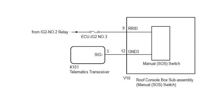
CAUTION / NOTICE / HINT
- NOTICE:
- ·
When replacing the telematics transceiver, make sure to replace it with a new one.
·Inspect the fuses and relays related to this system before inspecting the suspected areas below.
- HINT:
-
Depending on the parts that are replaced during vehicle inspection or maintenance, performing initialization, registration or calibration may be needed. Refer to Precaution for Telematics System.
-
Click hereAudio / Visual / Telematics>TELEMATICS>TELEMATICS SYSTEM (for eCall)>PRECAUTION
PROCEDURE
Disconnect the K151 telematics transceiver connector.
Disconnect the V18 roof console box sub-assembly (manual (SOS) switch) connector.
Measure the voltage according to the value(s) in the table below.
- Standard Voltage:
Tester Connection Switch Condition Specified Condition V18-9 (RRID) - Body Ground Ignition switch ON 11 to 14 V
Measure the resistance according to the value(s) in the table below.
- Standard Resistance:
Tester Connection Condition Specified Condition K151-3 (SIG-) - V18-12 (GND3) Always Below 1 Ω K151-3 (SIG-) or V18-12 (GND3) - Body ground Always 10 kΩ or higher
- Result:
Proceed to OK NG
OK
NG
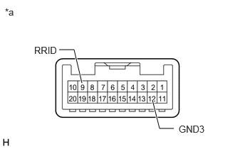
| *a | Component without harness connected
(Roof Console Box Sub-assembly (Manual (SOS) Switch)) |
Remove the roof console box sub-assembly (manual (SOS) switch).
Click hereVehicle Interior>LIGHTING (INT)>PERSONAL LIGHT>REMOVAL
Apply auxiliary battery voltage to the connector.
| Measurement Condition | Condition | Specified Condition |
|---|---|---|
| Auxiliary battery positive (+) → 9 (RRID)
Auxiliary battery negative (-) → 12 (GND3) |
Always | Manual (SOS) switch illumination comes on |
Check if the manual (SOS) switch illumination comes on.
- OK:
The manual (SOS) switch illumination comes on.
- Result:
Proceed to OK NG
OK
NG
Replace the telematics transceiver with a new one.
Click hereAudio / Visual / Telematics>TELEMATICS>TELEMATICS TRANSCEIVER>REMOVAL
- Result:
Proceed to NEXT
NEXT