N04C-VQ ENGINE CONTROL DIESEL THROTTLE BODY INSTALLATION
PROCEDURE

 26100
1.INSTALL DIESEL THROTTLE BODY
Remove any seal packing material from the contact surface.
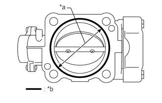
Apply a continuous bead of seal packing (width: 1.5 to 2.5 mm (0.0591 to 0.0984 in.)) as shown in the illustration.
- Seal packing:
Toyota Genuine Seal Packing Black, Three Bond 1207B or equivalent
| *a | 70 mm (2.75 in.) |
| *b | Seal Packing |
- NOTICE:
- ·
Remove any oil from contact surface.
·Install the diesel throttle body within 3 minutes of applying the seal packing.
·Do not run the engine for at least 2 hours after installation.
Install the diesel throttle body with the 2 bolts and 2 nuts.
- Torque:
29 N*m (291 kgf*cm, 21 ft.*lbf)
Connect the 2 connectors.
17030
2.INSTALL AIR HOSE ASSEMBLY
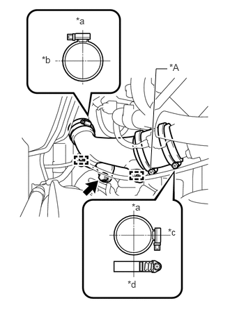
Connect the air hose assembly and install the bolt.
| *a | Upper Side |
| *b | Outside |
| *c | Inside |
| *d | Paint Mark |
- Torque:
18 N*m (184 kgf*cm, 13 ft.*lbf)
Tighten the hose clamp (intercooler air hose side), as shown in the illustration.
- Torque:
6.0 N*m (61 kgf*cm, 53 in.*lbf)
- HINT:
-
Tighten the screw at a rate of 2 seconds per turn.
Tighten the hose clamp (diesel throttle body side) until its end portion is overlapped to the paint mark.
- NOTICE:
-
Do not remove the hose clamp A.
Connect the 2 clamps.
44379A
3.INSTALL NO. 2 OIL RESERVOIR BRACKET
44360
4.INSTALL VANE PUMP OIL RESERVOIR ASSEMBLY
53712C
5.INSTALL FRONT FENDER APRON LH
Install the front fender apron LH with the 6 bolts.
- Torque:
7.0 N*m (71 kgf*cm, 62 in.*lbf)
51441D
6.INSTALL NO. 1 ENGINE UNDER COVER
58701A
7.INSTALL FRONT ENGINE SERVICE COVER PANEL SUB-ASSEMBLY
33506F
8.INSTALL FLOOR SHIFT CONTROL SHIFT LEVER RETAINER SUB-ASSEMBLY
58123A
9.INSTALL SHIFT AND SELECT LEVER SUPPORT WITH BOOTS
58420
10.INSTALL NO. 2 ENGINE SERVICE HOLE COVER ASSEMBLY
58734B
11.INSTALL REAR ENGINE SERVICE COVER WEATHERSTRIP
58410
12.INSTALL ENGINE SERVICE HOLE COVER
58521D
13.INSTALL ENGINE SERVICE HOLE COVER MAT