1HZ ENGINE MECHANICAL TIMING GEARS INSTALLATION
PROCEDURE

 13521
1.INSTALL CRANKSHAFT TIMING GEAR
Put the timing crankshaft timing gear with the timing mark facing frontward.
Align the timing gear set key with the key groove of the timing gear.
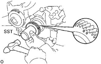
Using SST and a hammer. tap in the timing gear.
- SST
- 09223-00010
13613
2.INSTALL INJECTION PUMP DRIVE GEAR
Install the set key to the groove of the injection pump drive shaft.
Align the set key with the key groove of the injection pump drive gear and install the drive gear.
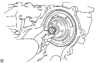
Install a new O-ring to the drive gear.
Install the injection pump drive gear set nut.
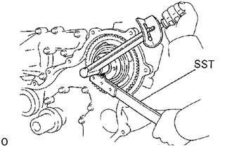
Using SST, torque the nut.
- SST
- 09330-00021
- Torque:
1,000 kg*cm (72 ft*lb, 98 N*m)
13525
3.INSTALL IDLE GEAR
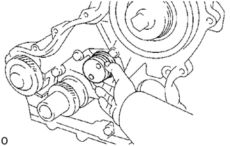
Install the idler gear shaft.
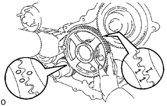
Align the idler gear timing marks "0" and "1" with the crankshaft timing gear mark "0" and injection pump drive gear timing mark "1" respectively, and mesh the gears.
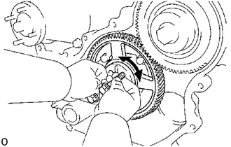
Align the thrust plate set bolt holes.
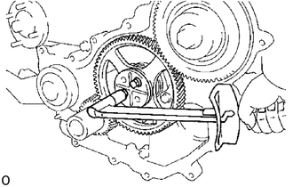
Install the thrust plate with the two bolts. Torque the bolts.
- Torque:
400 kg*cm (29 ft*lb, 39 N*m)
13522C
4.INSTALL PUMP DRIVE SHAFT GEAR
Align the pump drive shaft gear set key with the key groove of the drive shaft gear.
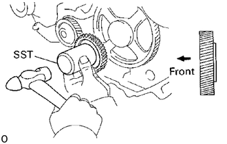
Using SST and a hammer, tap in the pump drive shaft gear.
- SST
- 09223-00010
11322F
5.INSTALL TIMING GEAR COVER
Remove any old packing (FIPG) material and be careful not to drop any oil on the contact surfaces of the timing gear cover and cylinder block.
Using a razor blade and gasket scraper, remove all the old packing (FlPG) material from the gasket surfaces and sealing groove.
Thoroughly clean all components to remove all the loose material.
Using a non-residue solvent, clean both sealing surfaces.
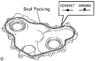
Apply seal packing to the timing gear cover as shown in the illustration.
- Seal packing:
Part No.08826-00080 or equivalent
Install a nozzle that has been cut to a 2 - 3 mm (0.08 - 0.12 in.) opening.
Parts must be assembled within 5 minutes of application. Otherwise the material must be removed and reapplied.
Immediately remove nozzle from the tube and reinstall cap.
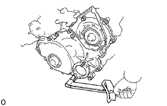
Install the timing gear cover with the fourteen bolts.
- Torque:
200 kg*cm (14 ft*lb, 20 N*m)
13471
6.INSTALL NO.1 CRANKSHAFT PULLEY
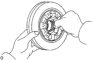
Install a new O-ring in the No.1 crankshaft pulley groove.
Align the pulley set key with the key groove of the pulley.
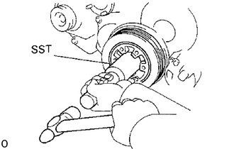
Using SST and a hammer, tap in the pulley.
- SST
- 09214-60010
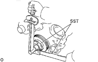
Using SST, install and torque the plate and bolt.
- Torque:
5,000 kg*cm (362 ft*lb, 490 N*m)
7.INSTALL NO.2 CRANKSHAFT PULLEY (1HZ and 1HD-T)
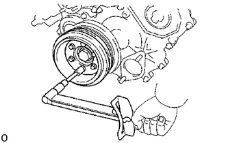
Install the No.2 crankshaft pulley with the six bolts.
- Torque:
250 kg*cm (18 ft*lb, 25 N*m)
29300
8.INSTALL VACUUM PUMP
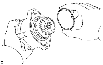
Install a new O-ring to the vacuum pump.
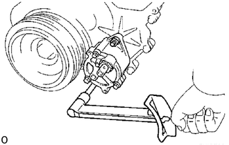
Install the vacuum pump with the two nuts.
- Torque:
400 kg*cm (29 ft*lb, 39 N*m)
9.INSTALL OIL PIPE
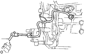
Install the oil pipe with the bolt, two union bolts and four new gaskets.
- Torque:
Bolt 200 kg*cm (14 ft*lb, 20 N*m)
Union bolt 185 kg*cm (13 ft*lb, 18 N*m)
11385
10.INSTALL CAMSHAFT OIL SEAL RETAINER
11.INSTALL PULLEYS AND TIMING BELT
12.INSTALL WATER PUMP PULLEY, FAN AND DRIVE BELT