1HZ ENGINE MECHANICAL CYLINDER HEAD INSTALLATION
CAUTION / NOTICE / HINT
PROCEDURE

 1.CHECK PISTON PROTRUSION AND SELECT CYLINDER HEAD GASKET
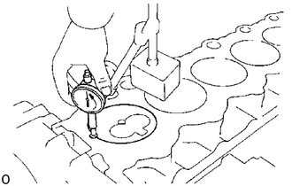
Check piston protrusions each cylinder
Clean the cylinder block solvent.
Set the piston of the cylinder to be measured to slightly befor TDC.
Place a dial indicator on the cylinder block, and set the dial indicator at 0 mm (0 in.)
- HINT:
- ·
Use a dial indicator measuring tip as shown in the illustration.
·Make sure that the measuring tip is sqaure to the cylinder block gasket surface and piston head when taking the measurments.
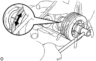
Find where the piston head protrudes most by slowly turning the crankshaft clockwise and counterclockwise.
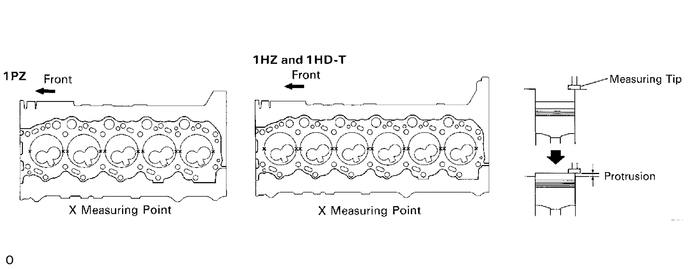
Measure each cylinder at two places as shown in the illustration, making a tatal of ten measurements (1PZ) or twelve measurements (1HZ and 1HD-T).
For the piston protrusion value of each cylinder, use the average of the two measurements of each cylinder.
- Protrusion:
- 1PZ and 1HZ:
0.405 - 0.655 mm (0.0159 - 0.0258 in.)
- 1HD-T:
0.475 - 0.725 mm (0.0187 - 0.0285 in,)
(When removing piston and connecting rod assembly)
If the protrusion is not as specified, remove the piston and connecting rod assembly and reinstall it.
Click hereEngine / Hybrid System>1HZ (ENGINE MECHANICAL)>CYLINDER BLOCK>CYLINDER BLOCK DISASSEMBLY
Click hereEngine / Hybrid System>1HZ (ENGINE MECHANICAL)>CYLINDER BLOCK>CYLINDER BLOCK ASSEMBLY
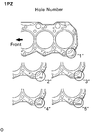
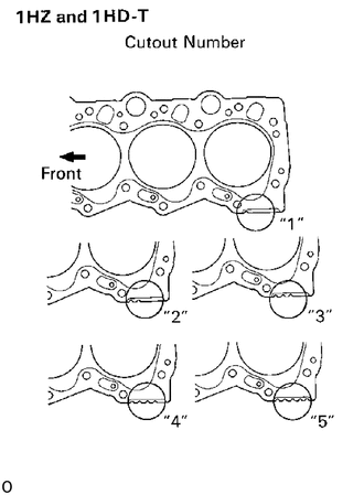
Select new cylinder head gasket
(1PZ)
- HINT:
-
There are five types of cylinder head gasket (hole number 1 to 5) installed at factory, but only three types for supply parts (hole number "1", "3" and "5"), so when replacing the gasket select from one of three types above.
- New cylinder head gasket thickness:
Hole number "1" 1 .16 - 1 .24 mm (0.0457 - 0.0488 in.)
Hole number "3" 1.26 - 1 .34 mm (0.0496 - 0.0528 in.)
Hole number "5" 1.36 - 1.44 mm (0.0535 - 0.0567 in.)
Select the largest piston protrusion value from the measurements made, then select the appropriate cylinder head gasket according to the table below.
| Piston protrusion mm (in.) | Gasket size |
|---|---|
| 0.455 (0.0179) or less | Use "1" |
| 0.456 - 0.555 (0.0180 - 0.0219) | Use "3" |
| 0.556 (0.0219) or more | Use "5" |
(1HZ and 1HD-T)
- HINT:
-
There are five types of cylinder head gasket ( cutout number 1 to 5) installed at factory, but only three types for supply parts (cutout number "1 ", "3" and "5"), so when replacing the gasket select from one of three types above.
- New cylinder head gasket thickness:
Cutout number "1" 1.15 - 1.25 mm (0.0453 - 0.0492 in.)
Cutout number "3" 1.25 - 1.35 mm (0.0492 - 0.0531 in.)
Cutout number "5" 1 .35 - 1.45 mm (0.0531 - 0.0571 in.)
Select the largest piston protrusion value from the measurements made, then select the appropriate cylinder head gasket according to the table below.
| Piston protrusion mm (in.) | Gasket size |
|---|---|
| 0.455 (0.0179) or less | Use "1" |
| 0.456 - 0.555 (0.0180 - 0.0219) | Use "3" |
| 0.556 (0.0246) or more | Use "5" |
| Piston protrusion mm (in.) | Gasket size |
|---|---|
| 0.525 (0.0207) or less | Use "1" |
| 0.526 - 0.625 (0.0207 - 0.0246) | Use "3" |
| 0.626 (0.0246) or more | Use "5" |
2.SET NO.1 CYLINDER TO BDC
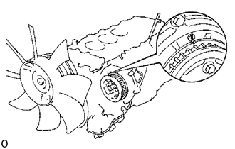
Turn the crankshaft pulley, and align the BDC mark of the timing gear cover with the No.1 flange groove of the No.2 camshaft timing pulley.
11101
3.INSTALL CYLINDER HEAD
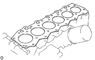
Place cylinder head on cylinder block
Place a new cylinder head gasket in position on the cylinder block.
- NOTICE:
-
Be careful of the installation direction.
Place the cylinder head in position on the cylinder head gasket.
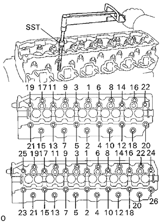
Install cylinder head bolts
- HINT:
- ·
The cylinder head bolts are tightened in three progressive steps.
·If any of bolts break or deform, replace them.
Apply a light coat of engine oil on the threads and under the heads of the cylinder head bolts.
First, using SST, install and uniformly tighten the twenty-two cylinder head bolts (1PZ) or twenty-six cylinder head bolts (1HZ and 1HD-T) in several passes in the sequence shown.
- Torque:
700 kg*cm (51 ft*lb, 68 N*m)
If any one of the bolts does not meet the torque specification, replace the bolt.
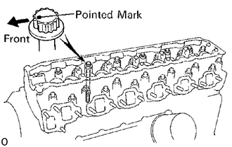
Mark the front of the cylinder head bolt head with paint.
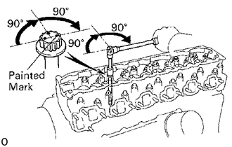
2nd, retighten the cylinder head bolts 90° in the numerical order shown above.
3rd, retighten cylinder head bolts by an additional 90° .
Check that the painted mark is now facing rearward.
13511
4.INSTALL CAMSHAFT
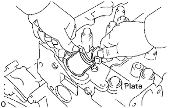
Install the camshaft thrust plate to the cylinder head.
Install the camshaft bearings to the No.1 bearing cap and No.1 journal of the cylinder head.
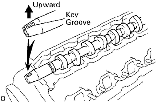
Place the camshaft on the cylinder head, facing the key groove upward.
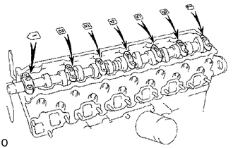
Install the six (1PZ) or seven (1HZ and 1HD-T) bearing caps in their proper locations.
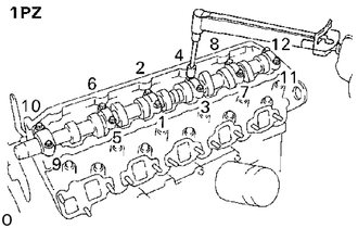
(1PZ)
Install and uniformly tighten the twelve bearing cap bolts in several passes in the sequence shown.
- Torque:
No.1 journal 250 kg*cm (18 ft*lb, 25 N*m)
Others 185 kg*cm (13 ft*lb, 18 N*m)
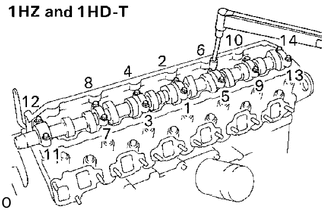
(1HZ and 1HD-T)
Install and uniformly tighten the fourteen bearing cap bolts in several passes in the sequence shown.
- Torque:
No.1 journal 250 kg*cm (18 ft*lb, 25 N*m)
Others 185 kg*cm (13 ft*lb, 18 N*m)
5.ADJUST VALVE CLEARANCE
Click hereEngine / Hybrid System>1HZ (ENGINE MECHANICAL)>VALVE CLEARANCE>ADJUSTMENT
- Valve clearance (Cold):
Intake 0.15 - 0.25 mm (0.006 - 0.010 in.)
Exhaust 0.35 - 0.45 mm (0.014 - 0.018 in.)
11385
6.INSTALL CAMSHAFT OIL SEAL RETAINER
Remove any old packing (FlPG) material and be careful not to drop any oil on the contact surfaces of the camshaft oil seal retainer and cylinder head.
Using a razor blade and gasket scraper, remove all the old packing (FIPG) material from the gasket surfaces and sealing groove.
Thoroughly clean all components to remove all the loose material.
Using a non-residue solvent. clean both sealing surfaces.
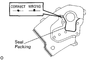
Apply seal packing to the camshaft oil seal retainer as shown in the illustration.
- Seal packing:
Part No.08826-00080 or equivalent
Install a nozzle that has been cut to a 2 - 3 mm( 0.08 - 0.12 in.) opening.
Parts must be assembled within 5 minutes of application. Otherwise the material must be removed and reapplied.
Immediately remove nozzle from the tube and reinstall cap.
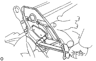
Install the retainer with the four bolts.
- Torque:
200 kg*cm (14 ft*lb, 20 N*m)
7.INSTALL PULLEYS AND TIMING BELT
17141
8.ASSEMBLY EXHAUST MANIFOLDS (1HZ and 1HD-T)
- NOTICE:
-
Do not align the ends.
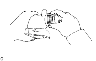
Remove all the O-ring material from the manifold grooves.
Install new O-rings.
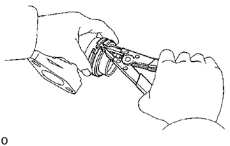
Using snap ring pliers, install the two manifold rings.
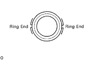
Position the manifold rings so that the ring ends are as shown.
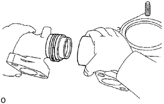
Install the manifold collar.
Assembly the front and rear manifolds.
17141
9.INSTALL EXHAUST MANIFOLD (1PZ and 1HZ)
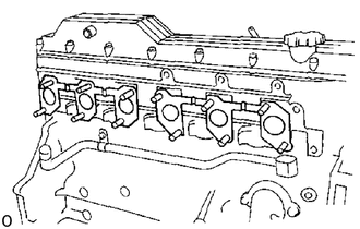
Install new gaskets in direction as shown in the illustration.
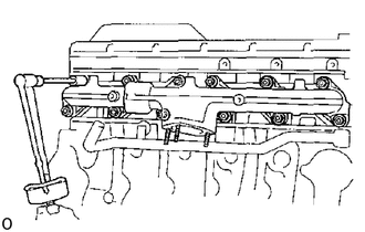
Install the exhaust manifold with the ten nuts (1PZ) or twelve nuts (1HZ).
- Torque:
400 kg*cm (29 ft*lb, 39 N*m)
- HINT:
-
Apply 330 kg*cm (24 ft*lb, 32 N*m) of torque when performing additional tightening of loosed nuts.
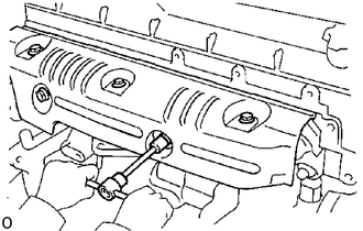
Install the heat insulator with the four bolts (1PZ) or five bolts (1HZ).
10.INSTALL TURBOCHARGER AND EXHAUST MANIFOLD (1HD-T)
19850
11.INSTALL GLOW PLUG
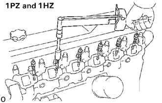
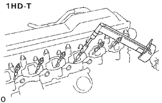
Using a 12 mm deep socket wrench, install the five glow plugs (1PZ) or six glow plugs (1HZ and 1HD-T).
- Torque:
130 kg*cm (9 ft*lb, 13 N*m)
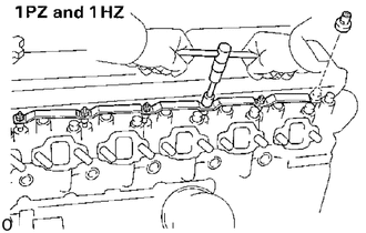
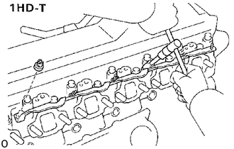
Install the glow plug connector with the five nuts (1PZ) or six nuts (1HZ and 1HD-T).
Install the five screw grommets (1PZ) and six screw grommets (1HZ and 1HD-T).
23600
12.INSTALL INJECTION NOZZLES
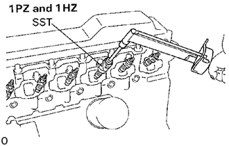
(1PZ and 1HZ)
Place new gaskets and the nozzle seats into the injection nozzle holes of the cylinder head.
Using SST, install the injection nozzles.
- SST
- 09268-64010
- Torque:
650 kg*cm (47 ft*lb, 64 N*m)
- NOTICE:
-
Over torquing could cause nozzle deformation and needle adhesion or other defects.
(1HD-T)
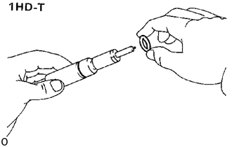
Install a new O-ring to the injection nozzle.
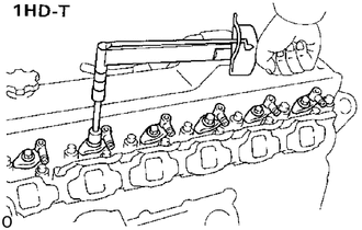
Place new nozzle seats into the injection nozzle holes of the cylinder head.
Install the injection nozzles with the washer and bolt.
- Torque:
400 kg*cm (29 ft*lb, 39 N*m)
23760
13.INSTALL NOZZLE LEAKAGE PIPE
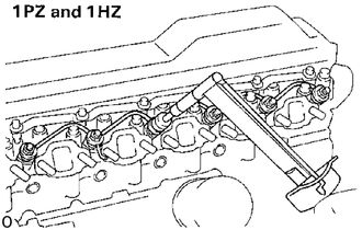
(1PZ and 1HZ)
(1PZ)
Install five new gaskets and the leakage pipe with the five nuts.
- Torque:
300 kg*cm (22 ft*lb, 29 N*m)
(1HZ)
Install six new gaskets and the leakage pipe with the six nuts.
- Torque:
300 kg*cm (22 ft*lb, 29 N*m)
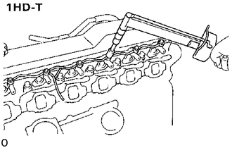
(1HD-T)
Install six new gaskets and the leakage pipe with the six nuts.
- Torque:
125 kg*cm (9 ft*lb, 12 N*m)
16331
14.INSTALL WATER OUTLET
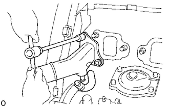
Install a new gasket and water outlet with the two nuts.
- Torque:
200 kg*cm (14 ft*lb, 20 N*m)
(1HD-T)
Connect the water by-pass hose.
17111
15.INSTALL INTAKE MANIFOLD
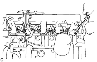
(1PZ)
Install five new gaskets and the intake manifold with the ten bolts and seal washers.
- Torque:
200 kg*cm (14 ft*lb, 20 N*m)
(1HZ and 1HD-T)
Install six new gaskets and the intake manifold with the twelve bolts and seal washers.
- Torque:
200 kg*cm (14 ft*lb, 20 N*m)
11452
16.INSTALL OIL DIPSTICK GUIDE AND OIL DIPSTICK
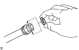
Install a new O-ring to the dipstick guide.
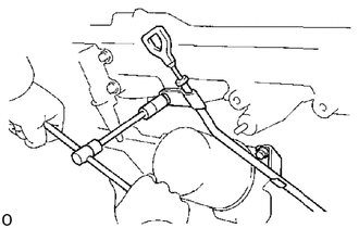
Install the oil dipstick guide assembly with the two bolts.
- Torque:
- Intake manifold side:
200 kg*cm (14 ft*lb, 20 N*m)
- Oil cooler cover side:
200 kg*cm (14 ft*lb, 20 N*m)
17.INSTALL INJECTION PIPES
17113
18.INSTALL INTAKE PIPE
19.FILL WIT ENGINE COOLANT
20.START ENGINE AND CHECK FOR LEAKS
21.RECHECK ENGINE COOLANT LEVEL AND OIL LEVEL