Home › Engine / Hybrid System › N04C-UH (ENGINE MECHANICAL) › CYLINDER HEAD
RM2850E _51 Engine / Hybrid System _073174 N04C-UH ENGINE MECHANICAL _0356076 CYLINDER HEAD A

N04C-UH ENGINE MECHANICAL  CYLINDER HEAD  INSTALLATION  


PROCEDURE

Hide 13751 1.INSTALL VALVE LIFTER

NOTICE:

Be sure to return the removed valve lifter to its original location.


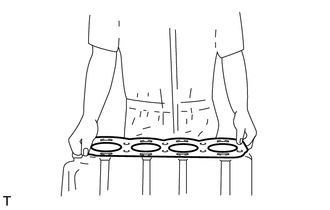
Hide 11115 2.INSTALL CYLINDER HEAD GASKET

a.
A151507

Install a new cylinder head gasket.

NOTICE:

Always use a new cylinder head gasket after cleaning the surface of the cylinder head sub-assembly, cylinder block and keep them free of dirt, water and grease.


Hide 11101 3.INSTALL CYLINDER HEAD SUB-ASSEMBLY

a.

Install the cylinder head sub-assembly over the dowels on the cylinder block.

HINT:

Since the cylinder head set bolts are unique to this engine, do not substitute them with ordinary bolts.
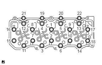


b.
A430231E01
0.729,0.365 0.906,0.552 0.177,0.188 10 false 21 1.344,0.365 1.521,0.552 0.177,0.188 10 false 19 1.979,0.365 2.156,0.552 0.177,0.188 10 false 20 2.604,0.365 2.781,0.552 0.177,0.188 10 false 22 3.052,0.917 3.229,1.083 0.177,0.167 10 true 17 3.063,1.323 3.24,1.49 0.177,0.167 10 true 18 1.052,0.74 1.229,0.927 0.177,0.188 10 false 8 1.688,0.75 1.865,0.938 0.177,0.188 10 false 1 2.313,0.74 2.49,0.927 0.177,0.188 10 false 9 0.208,0.906 0.385,1.094 0.177,0.188 10 false 16 0.219,1.292 0.396,1.479 0.177,0.188 10 false 15 0.74,1.615 0.917,1.802 0.177,0.188 10 false 11 1.385,1.625 1.563,1.813 0.177,0.188 10 false 3 2.01,1.625 2.188,1.813 0.177,0.188 10 false 6 2.604,1.635 2.781,1.823 0.177,0.188 10 false 14 0.719,0.875 0.896,1.063 0.177,0.188 10 false 12 1.375,0.875 1.552,1.063 0.177,0.188 10 false 4 2.01,0.875 2.188,1.063 0.177,0.188 10 false 5 2.583,0.875 2.76,1.063 0.177,0.188 10 false 13 1.063,1.115 1.24,1.302 0.177,0.188 10 false 7 1.688,1.125 1.865,1.313 0.177,0.188 10 false 2 2.281,1.125 2.458,1.313 0.177,0.188 10 false 10

Uniformly install and tighten the cylinder head set bolts (1 to 18) in the order shown in the illustration.

Torque:
60 N*m (612 kgf*cm, 44 ft.*lbf)


c.
A151508E05
1.917,1.21 1.917,1.747 false 1.801,1.822 1.97,1.982 0.169,0.16 10 *1 1.403,0.471 1.918,0.776 0.516,0.305 10 90° 2.695,0.471 3.211,0.776 0.516,0.305 10 90°

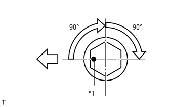
Mark the front side of each cylinder head set bolt head with paint as shown in the illustration.

Text in Illustration
*1 Paint
V100136

Front


d.

Retighten the cylinder head set bolts by 90° in the same order as step (b).


e.

Perform step (d) again.


f.

Check that each painted mark is now at a 180° angle to the front.


g.
A430231E01
0.729,0.365 0.906,0.552 0.177,0.188 10 false 21 1.344,0.365 1.521,0.552 0.177,0.188 10 false 19 1.979,0.365 2.156,0.552 0.177,0.188 10 false 20 2.604,0.365 2.781,0.552 0.177,0.188 10 false 22 3.052,0.917 3.229,1.083 0.177,0.167 10 true 17 3.063,1.323 3.24,1.49 0.177,0.167 10 true 18 1.052,0.74 1.229,0.927 0.177,0.188 10 false 8 1.688,0.75 1.865,0.938 0.177,0.188 10 false 1 2.313,0.74 2.49,0.927 0.177,0.188 10 false 9 0.208,0.906 0.385,1.094 0.177,0.188 10 false 16 0.219,1.292 0.396,1.479 0.177,0.188 10 false 15 0.74,1.615 0.917,1.802 0.177,0.188 10 false 11 1.385,1.625 1.563,1.813 0.177,0.188 10 false 3 2.01,1.625 2.188,1.813 0.177,0.188 10 false 6 2.604,1.635 2.781,1.823 0.177,0.188 10 false 14 0.719,0.875 0.896,1.063 0.177,0.188 10 false 12 1.375,0.875 1.552,1.063 0.177,0.188 10 false 4 2.01,0.875 2.188,1.063 0.177,0.188 10 false 5 2.583,0.875 2.76,1.063 0.177,0.188 10 false 13 1.063,1.115 1.24,1.302 0.177,0.188 10 false 7 1.688,1.125 1.865,1.313 0.177,0.188 10 false 2 2.281,1.125 2.458,1.313 0.177,0.188 10 false 10

Uniformly install and tighten the cylinder head set bolts (19 to 22) in the order shown in the illustration.

Torque:

55 N*m (561 kgf*cm, 41 ft.*lbf)


Hide 13819 4.INSTALL VALVE BRIDGE

NOTICE:

Be sure to install the removed valve bridge to its original location.


Hide 13781 5.INSTALL VALVE PUSH ROD

NOTICE:

Be sure to install the removed valve push rod to its original location.


Hide 13901 6.INSTALL NO. 1 VALVE ROCKER SHAFT SUB-ASSEMBLY

a.

Install the No. 1 rocker shaft sub-assembly onto the cylinder head sub-assembly.


b.

Apply engine oil to the rocker arm and valve push rod.
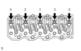

c.
A151465E03
2.904,0.326 3.009,0.477 0.104,0.152 10 5 2.284,0.326 2.388,0.477 0.104,0.152 10 3 1.657,0.326 1.761,0.477 0.104,0.152 10 1 1.031,0.326 1.136,0.477 0.104,0.152 10 2 0.413,0.326 0.518,0.477 0.104,0.152 10 4

Install the 5 bolts in the order shown in the illustration.

Torque:

69 N*m (699 kgf*cm, 51 ft.*lbf)


NOTICE:

Do not allow the valve push rod to interfere with the adjusting screw.


Hide 17141 8.INSTALL EXHAUST MANIFOLD

a.
A161408E02
0.894,0.316 1.064,0.48 0.17,0.165 10 *a 2.513,0.316 2.683,0.48 0.17,0.165 10 *b

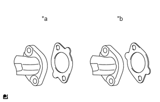
Install 4 new exhaust manifold gaskets onto the cylinder head sub-assembly as shown in the illustration.

Text in Illustration
*a INCORRECT
*b CORRECT


b.
A191456E01
1.226,3.212 1.408,3.379 0.182,0.167 10 *a 2.206,3.212 2.387,3.379 0.182,0.167 10 *a

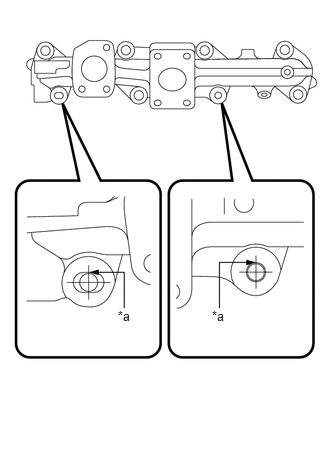
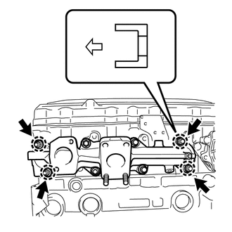
Temporarily install the exhaust manifold with the 8 nuts, 4 collars and 4 spacers.

Text in Illustration
*a Contact

HINT:
A347112

·

The stud bolts should contact the exhaust manifold as shown in the illustration.

·

Make sure to install the 4 collars in the correct direction.


Text in Illustration
V100136

Exhaust Manifold Side


c.
A175270E05
1.624,0.176 1.874,0.36 0.25,0.184 10 *a 1.659,2.196 1.874,2.387 0.215,0.191 10 *b 2.23,3.661 2.448,3.831 0.219,0.17 10 1 2.129,2.762 2.365,2.942 0.236,0.181 10 2 1.34,3.661 1.566,3.822 0.226,0.161 10 3 1.241,2.762 1.411,2.919 0.17,0.158 10 4 3.106,3.661 3.37,3.841 0.264,0.181 10 5 2.926,2.762 3.242,3.012 0.316,0.25 10 6 0.485,3.661 0.773,3.928 0.288,0.267 10 7 0.287,2.762 0.534,2.987 0.247,0.226 10 8 0.526,1.555 0.641,1.701 0.115,0.147 10 5 1.26,1.567 1.522,1.747 0.262,0.181 10 2, 6 2.148,1.567 2.413,1.728 0.265,0.161 10 4, 7 3.115,1.563 3.223,1.713 0.108,0.149 10 8 2.946,0.649 3.06,0.798 0.114,0.149 10 9 1.942,0.646 2.276,0.812 0.335,0.166 10 1, 10 1.088,0.623 1.425,0.792 0.337,0.169 10 3, 11 0.312,0.633 0.49,0.791 0.178,0.158 10 12

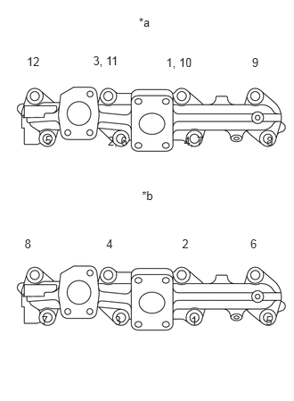
Tighten the 8 nuts in the order shown in the illustration.

Torque:

60 N*m (612 kgf*cm, 44 ft.*lbf)


Text in Illustration
*a New Exhaust Manifold
*b Used Exhaust Manifold


d.
A175270E06
1.676,0.372 1.874,0.53 0.198,0.157 10 *a 1.676,2.465 1.874,2.622 0.198,0.157 10 *b 0.19,2.874 0.534,3.038 0.344,0.164 10 8, 16 0.383,3.808 0.728,3.972 0.344,0.164 10 7, 15 2.965,3.808 3.309,3.972 0.344,0.164 10 5, 13 1.234,3.83 1.578,3.994 0.344,0.164 10 3, 11 2.13,3.83 2.419,3.994 0.289,0.164 10 1, 9 1.055,2.852 1.399,3.016 0.344,0.164 10 4, 12 1.921,2.852 2.265,3.016 0.344,0.164 10 2, 10 2.772,2.852 3.116,3.016 0.344,0.164 10 6, 14 0.386,1.712 0.666,1.866 0.279,0.155 10 1, 9 1.216,1.712 1.565,1.881 0.349,0.169 10 2, 10 2.152,1.712 2.524,1.873 0.372,0.161 10 3, 11 2.986,1.712 3.344,1.869 0.358,0.158 10 4, 12 2.808,0.759 3.15,0.926 0.342,0.167 10 5, 13 1.947,0.752 2.287,0.916 0.34,0.164 10 6, 14 1.078,0.744 1.421,0.908 0.343,0.164 10 7, 15 0.219,0.752 0.55,0.91 0.332,0.158 10 8, 16

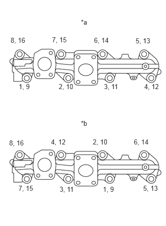
Check and re-tighten the 8 nuts in the order shown in the illustration.

Torque:

60 N*m (612 kgf*cm, 44 ft.*lbf)


Text in Illustration
*a New Exhaust Manifold
*b Used Exhaust Manifold


e.
A155964

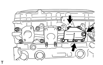
Install the exhaust manifold heat insulator with the 3 bolts.

Torque:

29 N*m (291 kgf*cm, 21 ft.*lbf)


Hide 17111 9.INSTALL INTAKE MANIFOLD

a.
A146603E03
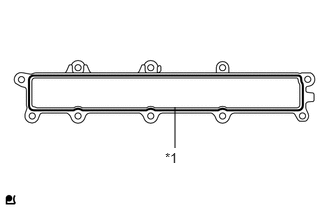
1.719,1.563 1.903,1.725 0.183,0.163 10 *1 1.822,1.541 1.822,1.116 false

Apply a continuous bead of seal packing (width: 2.2 mm (0.0866 in.)) as shown in the illustration.

Text in Illustration
*1 Seal Packing

Seal packing:

Toyota Genuine Seal Packing Black, Three Bond 1207B or equivalent


NOTICE:
·

Remove any oil from the contact surface.

·

Install the intake manifold within 3 minutes, and tighten the bolts within 15 minutes of applying the seal packing.

·

Do not start the engine for at least 2 hours after the installation.


b.

Install the intake manifold with the 8 bolts and 2 nuts.

Torque:

29 N*m (291 kgf*cm, 21 ft.*lbf)


Hide 16333 10.INSTALL WATER OUTLET HOUSING

Hide 16331 12.INSTALL WATER OUTLET SUB-ASSEMBLY

Hide 27020 13.INSTALL GENERATOR ASSEMBLY

Hide 16206C 14.INSTALL WATER BY-PASS PIPE SUB-ASSEMBLY

Hide 16206 15.INSTALL NO. 2 WATER BY-PASS PIPE SUB-ASSEMBLY

a.

Connect the water hose.


b.

Connect the water temperature sender gauge assembly connector.


c.

Install the No. 2 water by-pass pipe sub-assembly with the 2 bolts.

Torque:

29 N*m (291 kgf*cm, 21 ft.*lbf)


Hide 87208L 16.INSTALL WATER PIPE SUB-ASSEMBLY

Hide 23670 19.INSTALL INJECTOR ASSEMBLY

Hide 17201 20.INSTALL TURBOCHARGER SUB-ASSEMBLY

Hide 16400 21.INSTALL RADIATOR ASSEMBLY