1BZ-FPE LUBRICATION OIL PUMP INSTALLATION
PROCEDURE

 11301
1.INSTALL OIL PUMP (TIMING GEAR CASE)
Place a new gasket and the timing gear case in position.
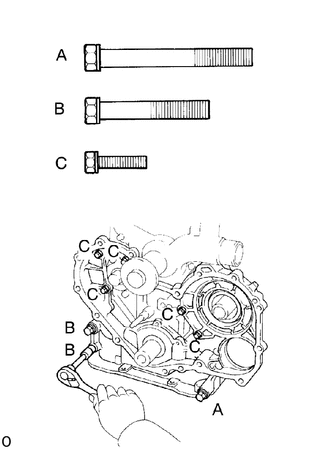
Install and uniformly tighten the 8 bolts in several passes.
- Torque:
14mm head: 44 N*m (449 kgf*cm, 32 ft*lbf)
12mm head: 21 N*m (214 kgf*cm, 15 ft*lbf)
- HINT:
-
Each bolt length is indicated in the illustration.
-
Bolt length:
-
A 85 mm (3.35 in.) for 14 mm head
-
B 60 mm (2.36 in.) for 14 mm head
-
C 25 mm (0.98 in.) for 12 mm head
Align the matchmarks on the injection pump and timing gear case.
Install the 2 nuts holding the injection pump flange to the timing gear case.
- Torque:
18.5 N*m (189 kgf*cm, 14 ft*lbf)
11429A
2.INSTALL STIFFENING PLATE
Remove any old packing (FIPG) material and be careful not to drop any oil on the contact surfaces of the stiffening plate and cylinder block.
Using a razor blade and gasket scraper, remove all the old packing (FIPG) material from the gasket surfaces and sealing groove.
Thoroughly clean all components to remove all the loose material.
Using a non-residue solvent, clean both sealing surfaces.
- NOTICE:
-
Do not use a solvent which will affect the painted surfaces.
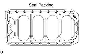
Apply seal packing to the oil pan as shown in the illustration.
- Seal packing:
Part No. 08826-00080 or equivalent
Install a nozzle that has been cut to a 4 - 5mm(0.16 - 0.20 in.) opening.
Parts must be assembled within 5 minutes of application. Otherwise the material must be removed and reapplied.
Immediately remove nozzle from the tube and reinstall cap.
Place the stiffening plate on the cylinder block.
15104
3.INSTALL OIL STRAINER AND OIL PIPE
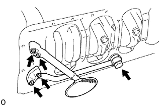
Install a new gasket and the oil strainer with the 2 nuts.
- Torque:
18.5 N*m (189 kgf*cm, 14 ft*lbf)
Install new 3 gaskets and oil pipe with the union bolt and 2 nuts.
- Torque:
Union bolt: 50 N*m (510 kgf*cm, 37 ft*lbf)
Nut: 18.5 N*m (189 kgf*cm, 14 ft*lbf)
12101
4.INSTALL OIL PAN
Remove any old packing (FIPG) material and be careful not to drop any oil on the contact surfaces of the oil pan and stiffening plate.
Using a razor blade and gasket scraper, remove all the old packing (FIPG) material from the gasket surfaces and sealing groove.
Thoroughly clean all components to remove all the loose material.
Using a non-residue solvent, clean both sealing surfaces.
- NOTICE:
-
Do not use a solvent which will affect the painted surfaces.
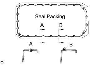
Apply seal packing to the oil pan as shown in the illustration.
- Seal packing:
Part No. 08826-00080 or equivalent
Install a nozzle that has been cut to a 4 - 5mm(0.16 - 0.20 in.) opening.
Parts must be assembled within 5 minutes of application. Otherwise the material must be removed and reapplied.
Immediately remove nozzle from the tube and reinstall cap.
Install the oil pan with the 17 bolts and 7 nuts. Uniformly tighten the bolts and nuts in several passes.
- Torque:
18.5 N*m (189 kgf*cm, 14 ft*lbf)
89491
5.INSTALL OIL LEVEL SENSOR
Install a new gasket to the oil pan.
Install the level sensor with the 4 bolts.
13523
6.INSTALL CAMSHAFT TIMING GEAR
Align the timing gear set key with the key groove of the timing gear.
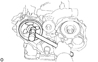
Using a plastic-faced hammer, lightly tap in the timing gear.
- NOTICE:
-
Avoid any impact to the camshaft.
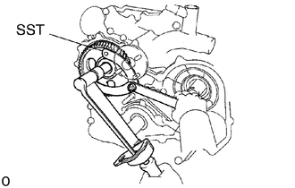
Using SST, install the plate washer and mount bolt.
- SST
- 09960-10010 (09962-01000, 09963-01000)
- Torque:
37.5 N*m (382 kgf*cm, 28 ft*lbf)
7.INSTALL CRANKSHAFT TIMING GEAR, IDLE GEAR, INJECTION PUMP DRIVE GEAR AND VACUUM PUMP
11302Q
8.INSTALL TIMING GEAR COVER AND CRANKSHAFT PULLEY
13901
9.INSTALL VALVE ROCKER SHAFT ASSEMBLY
10.INSTALL WATER PUMP PULLEY, FAN, FLUID COUPLING ASSEMBLY (FAN SPACER AND FAN) AND DRIVE BELT(S)
11452
11.INSTALL OIL DIPSTICK GUIDE AND OIL DIPSTICK
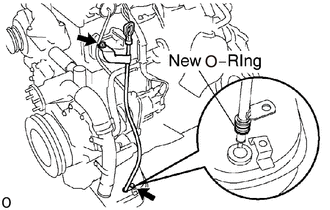
Install a new O-ring to the dipstick guide.
Apply soapy water to the O-ring.
Push in the dipstick guide end into the guide hole of the oil pan.
Install the oil dipstick guide with the 2 bolts.
Install the dipstick.
12.FILL WITH ENGINE OIL
13.START ENGINE AND CHECK FOR OIL LEAKS
14.RECHECK ENGINE OIL LEVEL
15.RECHECK VALVE CLEARANCE