1BZ-FPE ENGINE MECHANICAL TIMING GEAR INSTALLATION
PROCEDURE

 13521
1.INSTALL CRANKSHAFT TIMING GEAR
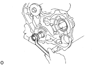
Check the set key on crankshaft facing upward.
If not, then turn the crankshaft with a crankshaft pulley mount bolt.
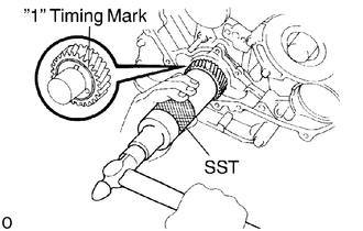
Put the timing gear on the crankshaft with the "1" timing mark of the timing gear facing forward.
Align the timing gear set key with the key groove of the timing gear.
Using SST and a hammer, tap in the timing gear.
- SST
- 09608-06041
13523
2.INSTALL CAMSHAFT TIMING GEAR AND CAMSHAFT ASSEMBLY
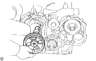
Install the camshaft into the cylinder block.
- NOTICE:
-
Be careful not to damage the camshaft bearing.
Install and torque the 2 bolts.
- Torque:
18.5 N*m (189 kgf*cm, 14 ft*lbf)
13503
3.INSTALL IDLER GEAR SHAFT
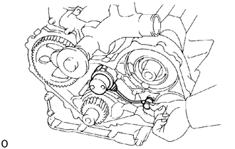
Temporarily install the idle gear shaft with the union bolt.
- NOTICE:
-
Do not tighten the union bolt.
13525
4.INSTALL IDLE GEAR
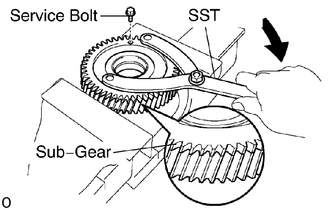
When the sub-gear and the idle gear have shifted, do the following work (a) and (b).
Using SST, align the holes of the idle gear and sub-gear by turning the sub-gear clockwise, and install a service bolt.
- SST
- 09960-10010 (09962-01000, 09963-00500)
Align the gear teeth of the idle gear and sub-gear, and tighten the service bolt.
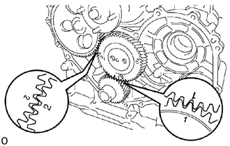
Align the idle gear timing marks "1" and "2" with the crankshaft gear timing mark "1" and camshaft gear timing mark "2" respectively, and mesh the gears.
Apply a light coat of engine oil on the threads and under the bolt heads.
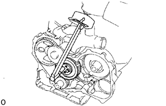
Install the thrust plate with the 2 bolts. Torque the bolts.
- Torque:
47.5 N*m (484 kgf*cm, 35 ft*lbf)
Remove the service bolt.
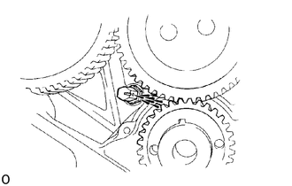
Check that the oil nozzle is in the position shown.
13503
5. TORQUE UNION BOLT FOR IDLE GEAR SHAFT
- Torque:
11 N*m (112 kgf*cm, 8 ft*lbf)
6.INSTALL INJECTION PUMP DRIVE GEAR
Apply MP grease to the drive gear spline, bearing and injection pump spline.
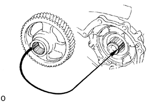
Align the spline toothless portions of the injection pump drive gear and injection pump, and install the injection pump drive gear.
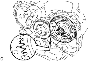
Align the idle gear timing mark "0" with the injection pump drive gear timing mark "0", and mesh the gears.
29300
7.INSTALL VACUUM PUMP
Install 2 new O-rings to vacuum pump.
Install the vacuum pump with the 2 bolts.
- Torque:
39 N*m (400 kgf*cm, 29 ft*lbf)
8.CHECK IDLE GEAR THRUST CLEARANCE
Click hereEngine / Hybrid System>1BZ-FPE (ENGINE MECHANICAL)>TIMING GEAR>REMOVAL
- Standard thrust clearance:
0.060 - 0.170 mm (0.0024 - 0.0067 in.)
- Maximum thrust clearance:
0.30 mm (0.118 in.)
11302Q
9.INSTALL TIMING GEAR COVER
Install a new gasket and the timing gear cover.
Align the 2 knock pins of the oil pump and lightly tap in the timing gear cover, using a plastic-faced hammer.
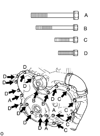
Install the 15 mount bolts.
- Torque:
14 mm head: 44 N*m (449 kgf*cm, 32 ft*lbf)
12 mm head: 21 N*m (214 kgf*cm, 15 ft*lbf)
- HINT:
-
Each bolt length is indicated in the illustration.
Bolt length:
A 85 mm (3.35 in.) for 14 mm head
B 77 mm (3.03 in.) for 12 mm head
C 40mm(1.57 in.) for 12 mm head
D 35mm(1.38 in.) for 12 mm head
19971G
10.INSTALL VACUUM PIPE
15301
11.INSTALL OIL DIPSTICK GUIDE AND DIPSTIC
16577C
12.INSTALL RADIATOR PIPE
Connect the radiator hose to the water pump.
Install the radiator pipe with the 2 bolts.
- Torque:
21 N*m (214 kgf*cm, 15 ft*lbf)
13470
13.INSTALL CRANKSHAFT PULLEY
Align the pulley set key with the key groove of the pulley.
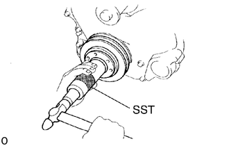
Using SST and a hammer, tap in the pulley.
- SST
- 09608-06041
Apply a light coat of engine oil on the threads and under the bolt head.
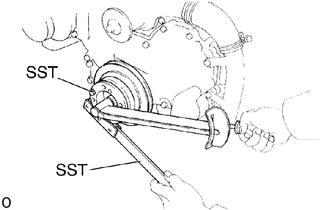
Using SST, install and torque the pulley mount bolt.
- SST
- 09330-00021
09213-58014 (90105-08076)
- Torque:
294 N*m (3,000 kgf*cm, 217 ft*lbf)
13751
14.DISPLACE VALVE LIFTERS
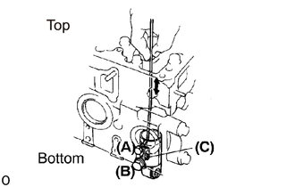
Remove bolt (A) and let the lifter slide down.
Install bolts (A) and (B) with new gaskets.
- Torque:
Bolt (A) 7.5 N*m (76 kgf*cm, 66 in.*lbf)
Bolt (B) 37.5 N*m (382 kgf*cm, 28 ft*lbf)
- HINT:
-
W hen inst alling bolt (B), c heck t hat t he hole f or bolt (B) is aligned with long hole (C) of valve lifter.
Check that the valve lifter can move up and down within the limits of long hole (C).
- NOTICE:
-
Be careful not to scratch the valve lifter.
15.INSTALL PUSH RODS
13901
16.INSTALL VALVE ROCKER SHAFT ASSEMBLY
11201
17.INSTALL CYLINDER HEAD COVER
19100P
18.INSTALL SPARK PLUGS
19100
19.INSTALL DISTRIBUTOR
19901A
20.CONNECT HIGH-TENSION CORDS TO SPARK PLUGS
17141
21.INSTALL EXHAUST MANIFOLD
22.INSTALL WATER PUMP PULLEY, FLUID COUPLING ASSEMBLY, FAN AND DRIVE BELTS
23.START ENGINE AND CHECK FOR LEAKS
24.CHECK ENGINE OIL LEVEL
25.READJUST VALVE CLEARANCE
26.READJUST DRIVE BELT(S)