ENGINE HOOD / DOOR BACK DOOR(for Emergency Door) REASSEMBLY
PROCEDURE

 75431A
1.INSTALL NO. 1 BACK DOOR EMBLEM
69410C
2.INSTALL BACK DOOR LOCK STRIKER PLATE ASSEMBLY
Using a T40 "TORX" socket wrench, install the back door lock striker plate assembly with the 2 "TORX" screws.
- Torque:
12 N*m (122 kgf*cm, 9 ft.*lbf)
67882C
3.INSTALL NO. 2 BACK DOOR WEATHERSTRIP
Attach the 8 clips to install the No. 2 back door weatherstrip.
Install the 2 clips.
67884C
4.INSTALL LOWER BACK DOOR WEATHERSTRIP LH
Remove the peeling paper from the face of the weatherstrip.
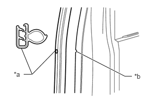
Align the paint marks with the positions on the back door flange and install a new lower back door weatherstrip LH.
| *a | Paint Mark |
| *b | Back Door Flange |
- NOTICE:
- ·
After the installation, check that the corners are properly installed.
·Always align the paint mark when installing the part. If the paint mark position is out of place, water leaks may occur.
- HINT:
-
To easily install the lower back door weatherstrip LH, first install the area with the paint mark. Then install the part toward the corners and push any excess length into the corners.
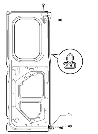
Install the 4 clips.
| *a | Double-sided Tape |
69350Q
5.INSTALL UPPER BACK DOOR LOCK ASSEMBLY
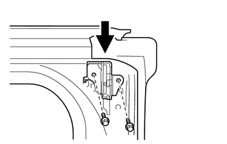
Insert the link into the back door panel as indicated by the arrow in the illustration and install 2 bolts to upper back door lock assembly.
- Torque:
24 N*m (245 kgf*cm, 18 ft.*lbf)
- NOTICE:
-
Be careful link not to be catch in the inside.
69380C
6.INSTALL LOWER BACK DOOR LOCK ASSEMBLY
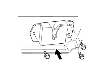
Insert the link into the back door panel as indicated by the arrow in the illustration and install 3 bolts to lower back door lock assembly.
- Torque:
7.5 N*m (76 kgf*cm, 66 in.*lbf)
- NOTICE:
-
Be careful link not to be catch in the inside.
69042
7.INSTALL LOWER BACK DOOR STOPPER SUB-ASSEMBLY
Install the lower back door stopper sub-assembly with the 2 bolts.
- Torque:
12 N*m (122 kgf*cm, 9 ft.*lbf)
69321
8.INSTALL BACK DOOR LOCK COVER
Attach the 2 claws and install the back door lock cover.
Install the bolt.
- Torque:
5.0 N*m (51 kgf*cm, 44 in.*lbf)
69690
9.INSTALL BACK DOOR REMOTE CONTROL ASSEMBLY
Install the back door remote control assembly with the 2 bolts.
- Torque:
5.0 N*m (51 kgf*cm, 44 in.*lbf)
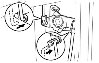
Install the 2 links to the back door remote control assembly.
69212B
10.INSTALL BACK DOOR INSIDE HANDLE
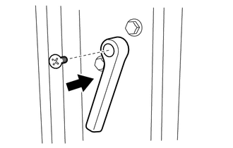
Install the back door inside handle in the direction indicated by the arrow in the illustration.
Install the screw.
67847
11.INSTALL BACK DOOR SERVICE HOLE COVER RH
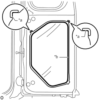
Apply new butyl tape to the door panel.
Install a new back door service hole cover RH using the reference points on the back door panel.
- NOTICE:
-
There should be no wrinkles or folds after installing the back door service hole cover RH.
| *a | Reference Point |
| *b | Butyl Tape |
64780C
12.INSTALL BACK DOOR TRIM PANEL ASSEMBLY RH
Install the back door trim panel assembly RH with the 14 clips.
68957
13.INSTALL BACK DOOR STAY BRACKET (w/ No. 1 Back Door Stay)
Install the back door stay bracket and No. 1 back door stay with the 3 bolts.
- Torque:
5.0 N*m (51 kgf*cm, 44 in.*lbf)
67883E
14.INSTALL NO. 3 BACK DOOR WEATHERSTRIP
Attach the 15 clips to install the No. 3 back door weatherstrip.
69042
15.INSTALL LOWER BACK DOOR STOPPER SUB-ASSEMBLY
Install the lower back door stopper sub-assembly with the 2 bolts.
- Torque:
12 N*m (122 kgf*cm, 9 ft.*lbf)
16.INSTALL BACK DOOR LOCK CYLINDER ASSEMBLY
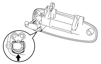
Install the back door lock cylinder assembly with the spring.
69220
17.INSTALL BACK DOOR OUTSIDE HANDLE ASSEMBLY LH
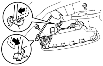
Install the back door outside handle assembly LH with the 2 bolts.
- Torque:
5.0 N*m (51 kgf*cm, 44 in.*lbf)
Connect the 2 links.
86790D
18.INSTALL TELEVISION CAMERA ASSEMBLY RR (w/ Rear Monitor)
19.INSTALL BACK DOOR OUTSIDE GARNISH
67848
20.INSTALL BACK DOOR SERVICE HOLE COVER LH
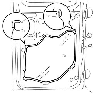
Apply new butyl tape to the back door panel.
Install a new back door service hole cover LH using the reference points on the front door panel.
- NOTICE:
-
There should be no wrinkles or folds after installing the back door service hole cover LH.
| *a | Reference Point |
| *b | Butyl Tape |
84231C
21.INSTALL COURTESY LIGHT SWITCH
69789
22.INSTALL BACK DOOR LOCK CONTROL LINK SILENCER (w/o Handle)
Remove any non-drying sealer on the body with non-residue solvent.
Remove the peeling paper from the face of the back door lock control link silencer.
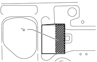
Install the back door lock control link silencer.
| *a | Double-sided Tape |
69350
23.INSTALL BACK DOOR LOCK ASSEMBLY (w/o Handle)
69291
24.INSTALL BACK DOOR INSIDE HANDLE ASSEMBLY (w/o Handle)
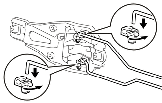
Install the 2 links.
Install the back door inside handle assembly with the 2 screws.
67853C
25.INSTALL NO. 3 BACK DOOR SERVICE HOLE COVER (w/o Handle)
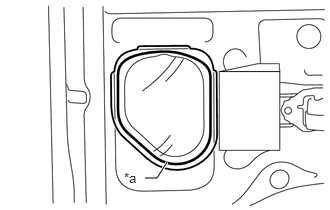
Apply new butyl tape to the back door panel.
Install a new No. 3 back door service hole cover using the reference points on the front door panel.
- NOTICE:
-
There should be no wrinkles or folds after installing the No. 3 back door service hole cover.
| *a | Butyl Tape |
64790C
26.INSTALL BACK DOOR TRIM PANEL ASSEMBLY LH (w/o Handle)
Install the back door trim panel assembly LH with the 12 clips.
69278D
27.INSTALL DOOR INSIDE HANDLE BEZEL LH (w/o Handle)
Attach the 3 claws to install the door inside handle bezel LH.
Install the screw.
67807
28.INSTALL BACK DOOR SERVICE HOLE COVER SUB-ASSEMBLY (w/o Handle)
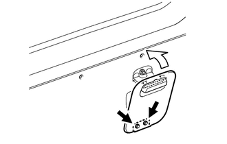
Install the back door service hole cover sub-assembly with the 2 bolts.
- Torque:
5.0 N*m (51 kgf*cm, 44 in.*lbf)
Close the back door service hole cover sub-assembly.

|
Bolt |

|
Install in this Direction |
69350
29.INSTALL BACK DOOR LOCK ASSEMBLY (w/ Handle)
64561
30.INSTALL EMERGENCY BACK DOOR WINDSHIELD GLASS (w/ Handle)
64562
31.INSTALL BACK DOOR WINDOW EMERGENCY GLASS WEATHERSTRIP OUTER (w/ Handle)
64563
32.INSTALL BACK DOOR WINDOW EMERGENCY GLASS WEATHERSTRIP INNER (w/ Handle)
67297
33.INSTALL BACK DOOR COVER WEATHERSTRIP (w/ Handle)
Clean the back door cover weatherstrip installation surface with non-residue solvent.
Install the new back door cover weatherstrip.
67199
34.INSTALL BACK DOOR HANDLE COVER (w/ Handle)
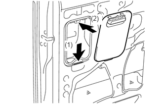
Install the back door handle cover as indicated by the arrows in the order shown in the illustration.
64790C
35.INSTALL BACK DOOR TRIM PANEL ASSEMBLY LH (w/ Handle)
Attach the 12 clips to install the back door trim panel assembly LH.
74611B
36.INSTALL ASSIST GRIP
Install the assist grip with the 2 screws.
74617F
37.INSTALL ASSIST GRIP PLUG
Attach the 4 claws and install the assist grip plug.
68957
38.INSTALL BACK DOOR STAY BRACKET (w/ No. 1 Back Door Stay)
Install the back door stay bracket and No.1 back door stay with the 3 bolts.
- Torque:
5.0 N*m (51 kgf*cm, 44 in.*lbf)