Home › Brake › BRAKE CONTROL / DYNAMIC CONTROL SYSTEMS › ANTI-LOCK BRAKE SYSTEM(w/ Brake pedal Load Sensing Switch) › 2017.01–2018.07
RM2850E _54 Brake _073264 BRAKE CONTROL / DYNAMIC CONTROL SYSTEMS _0356878 ANTI-LOCK BRAKE SYSTEM(w/ Brake pedal Load Sensing Switch) J

BRAKE CONTROL / DYNAMIC CONTROL SYSTEMS  ANTI-LOCK BRAKE SYSTEM(w/ Brake pedal Load Sensing Switch)  TC and CG Terminal Circuit  


DESCRIPTION

Connecting terminals TC and CG of the DLC3 causes the ECU to display the DTC by blinking the ABS warning light.

WIRING DIAGRAM
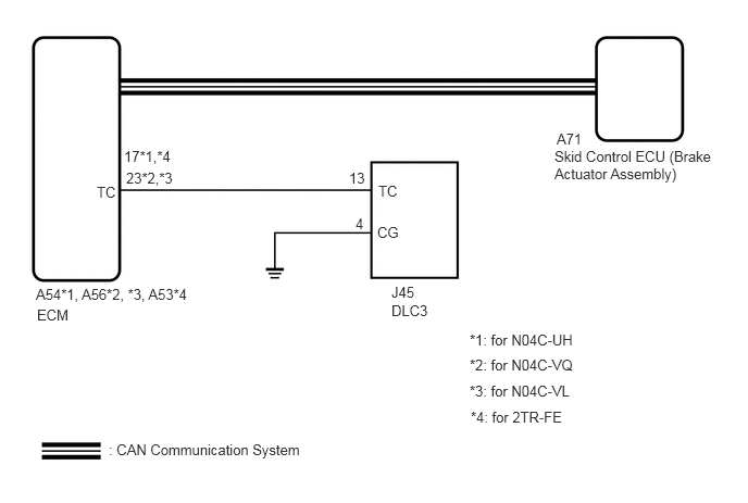
C256466E48
0.927,1.76 1.24,1.958 0.313,0.198 10 false TC 3.625,1.75 3.938,1.948 0.313,0.198 10 false TC 3.615,2.146 3.927,2.344 0.313,0.198 10 false CG 3.75,2.719 4.094,2.927 0.344,0.208 10 false J45 3.75,2.896 4.219,3.104 0.469,0.208 10 false DLC3 3.344,1.625 3.656,1.823 0.313,0.198 10 false 13 3.406,2.063 3.625,2.229 0.219,0.167 10 false 4 1.188,1.417 1.844,1.594 0.656,0.177 10 false 17*1,*4 1.208,1.625 1.802,1.813 0.594,0.188 10 false 23*2,*3 0.344,2.74 2.052,2.917 1.708,0.177 10 false A54*1, A56*2, *3, A53*4 0.354,2.938 0.854,3.125 0.5,0.188 10 false ECM 5.333,1.25 5.833,1.438 0.5,0.188 10 false A71 5.313,1.417 6.875,1.802 1.563,0.385 10 false Skid Control ECU (Brake Actuator Assembly) 1.042,4.229 3.208,4.458 2.167,0.229 10 false : CAN Communication System 4.5,3.177 5.688,3.406 1.188,0.229 10 false *1: for N04C-UH 4.5,3.417 5.688,3.646 1.188,0.229 10 false *2: for N04C-VQ 4.5,3.667 5.688,3.896 1.188,0.229 10 false *3: for N04C-VL 4.51,3.917 5.698,4.146 1.188,0.229 10 false *4: for 2TR-FE

CAUTION / NOTICE / HINT

NOTICE:

When replacing the skid control ECU (brake actuator assembly), perform zero point calibration and store system information (Click hereBrake>BRAKE CONTROL / DYNAMIC CONTROL SYSTEMS>ANTI-LOCK BRAKE SYSTEM(w/ Brake pedal Load Sensing Switch)>CALIBRATION).


PROCEDURE

1.CHECK CAN COMMUNICATION LINE

A

2.INSPECT DLC3

B

2.INSPECT DLC3
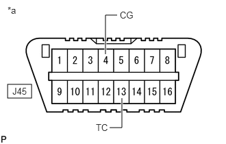
a.
C245481E37
0.115,1.281 0.479,1.49 0.365,0.208 1.604,0.823 1.604,0.229 1.604,0.229 1.781,0.229 true 1.667,1.938 1.854,1.938 1.854,1.938 1.854,1.49 true 0.115,0.073 0.427,0.271 0.313,0.198 10 false *a 1.823,0.146 2.135,0.344 0.313,0.198 10 false CG 1.458,1.854 1.771,2.052 0.313,0.198 10 false TC 0.188,1.302 0.51,1.5 0.323,0.198 10 false J45

Turn the ignition switch to ON.


b.

Measure the voltage according to the value(s) in the table below.

Standard Voltage:
Tester Connection Condition Specified Condition
J45-13 (TC) - J45-4 (CG) Ignition switch ON 11 to 14 V


Text in Illustration
*a Front view of DLC3


Result:
Proceed to
OK
NG


OK

3.REPLACE ECM

NG

4.CHECK HARNESS AND CONNECTOR (TC of DLC3 - ECM)
3.REPLACE ECM
SST
09843-18040  

a.

Turn the ignition switch to ON.


b.

Replace the ECM.

Refer to the ECM removal procedures:
Item See page
N04C-UH (Click here)
N04C-VQ (Click here)
N04C-VL (Click here)
2TR-FE (Click here)


c.
C245481E37
0.115,1.281 0.479,1.49 0.365,0.208 1.604,0.823 1.604,0.229 1.604,0.229 1.781,0.229 true 1.667,1.938 1.854,1.938 1.854,1.938 1.854,1.49 true 0.115,0.073 0.427,0.271 0.313,0.198 10 false *a 1.823,0.146 2.135,0.344 0.313,0.198 10 false CG 1.458,1.854 1.771,2.052 0.313,0.198 10 false TC 0.188,1.302 0.51,1.5 0.323,0.198 10 false J45

Using SST, connect terminals 13 (TC) and 4 (CG) of the DLC3.

Text in Illustration
*a Front view of DLC3


d.

Check that the ABS warning light is blinking.

OK:

The ABS warning light is blinking.


Result:
Proceed to
OK
NG


OK

END

NG

4.CHECK HARNESS AND CONNECTOR (TC of DLC3 - ECM)
a.

Turn the ignition switch off.


b.

for N04C-UH:

i.

Disconnect the A54 ECM connector.


c.

for N04C-VQ, N04C-VL:

i.

Disconnect the A56 ECM connector.


d.

for 2TR-FE:

i.

Disconnect the A53 ECM connector.


e.

Measure the resistance according to the value(s) in the table below.

Standard Resistance:
for N04C-UH:
Tester Connection Condition Specified Condition
A54-17 (TC) - J45-13 (TC) Always Below 1 Ω
A54-17 (TC) or J45-13 (TC) - Body ground Always 10 kΩ or higher

for N04C-VQ, N04C-VL:
Tester Connection Condition Specified Condition
A56-23 (TC) - J45-13 (TC) Always Below 1 Ω
A56-23 (TC) or J45-13 (TC) - Body ground Always 10 kΩ or higher

for 2TR-FE:
Tester Connection Condition Specified Condition
A53-17 (TC) - J45-13 (TC) Always Below 1 Ω
A53-17 (TC) or J45-13 (TC) - Body ground Always 10 kΩ or higher


Result:
Proceed to
OK
NG


OK

5.CHECK HARNESS AND CONNECTOR (CG of DLC3 - BODY GROUND)

NG

REPAIR OR REPLACE HARNESS OR CONNECTOR

5.CHECK HARNESS AND CONNECTOR (CG of DLC3 - BODY GROUND)
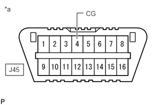
a.
C245481E38
0.115,1.333 0.49,1.573 0.375,0.24 1.604,0.813 1.604,0.271 1.604,0.271 1.74,0.271 true 0.094,0.104 0.406,0.302 0.313,0.198 10 false *a 1.792,0.198 2.135,0.406 0.344,0.208 10 false CG 0.188,1.365 0.531,1.573 0.344,0.208 10 false J45

Measure the resistance according to the value(s) in the table below.

Standard Resistance:
Tester Connection Condition Specified Condition
J45-4 (CG) - Body ground Always Below 1 Ω


Text in Illustration
*a Front view of DLC3


Result:
Proceed to
OK
NG


OK

6.REPLACE ECM

NG

REPAIR OR REPLACE HARNESS OR CONNECTOR

6.REPLACE ECM
SST
09843-18040  

a.

Turn the ignition switch to ON.


b.

Replace the ECM.

Refer to the ECM removal procedures:
Item See page
N04C-UH (Click here)
N04C-VQ (Click here)
N04C-VL (Click here)
2TR-FE (Click here)


c.
C245481E37
0.115,1.281 0.479,1.49 0.365,0.208 1.604,0.823 1.604,0.229 1.604,0.229 1.781,0.229 true 1.667,1.938 1.854,1.938 1.854,1.938 1.854,1.49 true 0.115,0.073 0.427,0.271 0.313,0.198 10 false *a 1.823,0.146 2.135,0.344 0.313,0.198 10 false CG 1.458,1.854 1.771,2.052 0.313,0.198 10 false TC 0.188,1.302 0.51,1.5 0.323,0.198 10 false J45

Using SST, connect terminals 13 (TC) and 4 (CG) of the DLC3.

Text in Illustration
*a Front view of DLC3


d.

Check that the ABS warning light is blinking.

OK:

The ABS warning light is blinking.


Result:
Proceed to
OK
NG


OK

END

NG