N04C-VQ CHARGING GENERATOR INSTALLATION
PROCEDURE

 27020
1.INSTALL GENERATOR ASSEMBLY
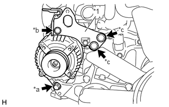
Temporarily install the generator assembly with the bolt A.
Temporarily install the generator bracket with the bolt B to the generator assembly.
Install the generator bracket with the 2 bolts C.
- Torque:
62 N*m (632 kgf*cm, 46 ft.*lbf)
Tighten the bolt A and bolt B.
- Torque:
- for bolt A:
29 N*m (296 kgf*cm, 21 ft.*lbf)
- for bolt B:
55 N*m (561 kgf*cm, 41 ft.*lbf)
| *1 | Generator Bracket |
| *a | Bolt A |
| *b | Bolt B |
| *c | Bolt C |
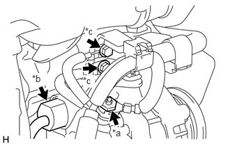
Install the nut to connect the terminal B.
- Torque:
9.8 N*m (100 kgf*cm, 87 ft.*lbf)
Connect the connector.
Install the wire harnesses with the 2 bolts to the generator bracket.
- Torque:
19 N*m (194 kgf*cm, 14 ft.*lbf)
| *a | Nut |
| *b | Connector |
| *c | Bolt |
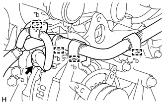
Install the terminal cap.
Attach the clamps.
| *a | Terminal Cap |
| *b | Clamp |
17113D
2.INSTALL NO. 1 INTAKE PIPE
16701
3.INSTALL FAN SHROUD SUB-ASSEMBLY
58701A
4.INSTALL FRONT ENGINE SERVICE COVER PANEL SUB-ASSEMBLY
33506F
5.INSTALL FLOOR SHIFT CONTROL SHIFT LEVER RETAINER SUB-ASSEMBLY
58123A
6.INSTALL SHIFT AND SELECT LEVER SUPPORT WITH BOOTS
58420
7.INSTALL NO. 2 ENGINE SERVICE HOLE COVER ASSEMBLY
58521D
8.INSTALL ENGINE SERVICE HOLE COVER MAT
58734B
9.INSTALL REAR ENGINE SERVICE COVER WEATHERSTRIP
58410
10.INSTALL ENGINE SERVICE HOLE COVER
11.CONNECT CABLE TO NEGATIVE BATTERY TERMINAL
- NOTICE:
-
When disconnecting the cable, some systems need to be initialized after the cable is reconnected.
-
Click hereGeneral>INTRODUCTION>REPAIR INSTRUCTION>INITIALIZATION