A861E AUTOMATIC TRANSMISSION / TRANSAXLE AUTOMATIC TRANSMISSION SYSTEM P0705 Transmission Range Sensor "A" Circuit (PRNDL Input)
DESCRIPTION
The Park/Neutral Position (PNP) switch detects the shift lever position and sends signals to the transmission control ECU assembly.
| DTC No. | Detection Item | DTC Detection Condition | Trouble Area | Warning Indicate | Memory |
|---|---|---|---|---|---|
| P0705 | Transmission Range Sensor "A" Circuit (PRNDL Input) | 1. Diagnosis Condition 2. Malfunction Status 3. Malfunction Time 4. Other
DTC Detection Condition 1:
1.
Ignition switch ON 2.
P, R, N, D, 3 and 2 signals are not input (with all switches off) 3.
60 seconds or more 4.
1 trip detection logic DTC Detection Condition 2:
1.
Ignition switch ON 2.
At least 2 signals of P, R, N, D, 3 and 2 are input 3.
2 seconds or more 4.
1 trip detection logic |
·
Wire harness or connector (P, R, N, D, 3, 2 signal circuit) ·
Park/neutral position switch assembly ·
Transmission control ECU assembly |
O/D OFF Indicator Light: Blinking | DTC stored |
CONFIRMATION DRIVING PATTERN
- HINT:
-
After the repair, clear the DTCs and perform the following procedure to check that DTCs are not output.
Turn the ignition switch to ON.
Wait with the shift lever in each position (P, R, N, D, 4 and 2/L) for 60 seconds or more.
Check for DTCs again.
WIRING DIAGRAM
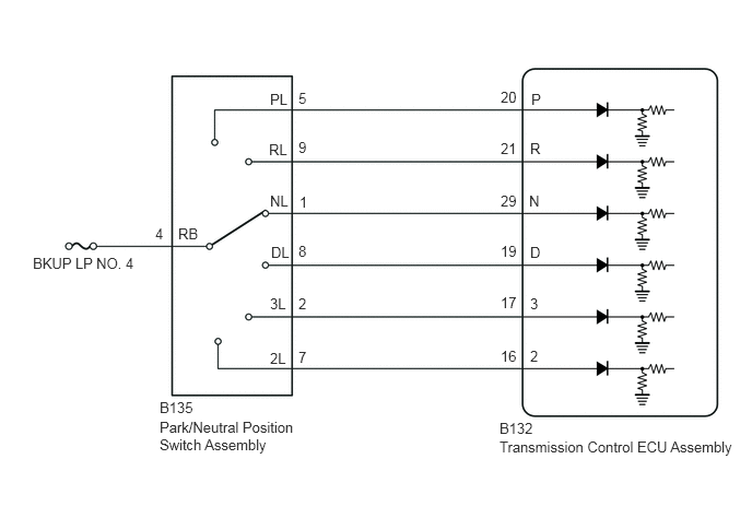
CAUTION / NOTICE / HINT
- NOTICE:
- ·
Inspect the fuses for circuits related to this system before performing the following inspection procedure.
·Perform initialization when parts related to the automatic transmission are replaced.
Click hereDrivetrain>A861E (AUTOMATIC TRANSMISSION / TRANSAXLE)>AUTOMATIC TRANSMISSION SYSTEM>INITIALIZATION
PROCEDURE
Connect the GTS to the DLC3.
Turn the ignition switch to ON.
Turn the GTS on.
Enter the following menus: Powertrain / ECT / Data List.
Accordance to the display on the GTS, read the Data List.
| Tester Display | Measurement Item | Range | Normal Condition | Diagnostic Note |
|---|---|---|---|---|
| Shift SW Status (P Range) | Park/neutral position switch status | OFF or ON | ·
OFF: Shift lever not in P ·
ON: Shift lever in P |
- |
| Shift SW Status (R Range) | Park/neutral position switch status | OFF or ON | ·
OFF: Shift lever not in R ·
ON: Shift lever in R |
- |
| Shift SW Status (2 Range) | Park/neutral position switch status | OFF or ON | ·
OFF: Shift lever not in 2/L ·
ON: Shift lever in 2/L |
- |
| Shift SW Status (N Range) | Park/neutral position switch status | OFF or ON | ·
OFF: Shift lever not in N ·
ON: Shift lever in N |
- |
| Shift SW Status (D Range) | Park/neutral position switch status | OFF or ON | ·
OFF: Shift lever not in D ·
ON: Shift lever in D |
- |
| Shift SW Status (4 Range) | Park/neutral position switch status | OFF or ON | ·
OFF: Shift lever not in 4 ·
ON: Shift lever in 4 |
- |
- Result:
Result Proceed to Data List values are normal A Data List values are not normal B
A
Click hereGeneral>INTRODUCTION>HOW TO TROUBLESHOOT ECU CONTROLLED SYSTEMS>HOW TO PROCEED WITH TROUBLESHOOTING
B
Disconnect the park/neutral position switch assembly connector.
Turn the ignition switch to ON.
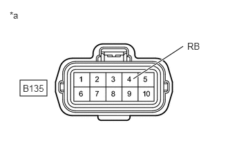
| *a | Front view of wire harness connector
(to Park/Neutral Position Switch Assembly) |
Measure the voltage according to the value(s) in the table below.
- Standard Voltage:
Tester Connection Switch Condition Specified Condition B135-4 (RB) - Body ground Ignition switch ON 11 to 14 V
- Result:
Proceed to OK NG
OK
NG
Disconnect the park/neutral position switch assembly connector.
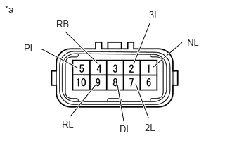
| *a | Component without harness connected
(Park/Neutral Position Switch Assembly) |
Measure the resistance according to the value(s) in the table below.
- Standard Resistance:
Tester Connection Condition Specified Condition 4 (RB) - 5 (PL) Shift lever in P Below 1 Ω Shift lever not in P 10 kΩ or higher 4 (RB) - 9 (RL) Shift lever in R Below 1 Ω Shift lever not in R 10 kΩ or higher 4 (RB) - 1 (NL) Shift lever in N Below 1 Ω Shift lever not in N 10 kΩ or higher 4 (RB) - 8 (DL) Shift lever in D Below 1 Ω Shift lever not in D 10 kΩ or higher 4 (RB) - 2 (3L) Shift lever in 4 Below 1 Ω Shift lever not in 4 10 kΩ or higher 4 (RB) - 7 (2L) Shift lever in 2/L Below 1 Ω Shift lever not in 2/L 10 kΩ or higher
- Result:
Proceed to OK NG
OK
NG
Click hereDrivetrain>A861E (AUTOMATIC TRANSMISSION / TRANSAXLE)>PARK / NEUTRAL POSITION SWITCH>REMOVAL
Disconnect the transmission control ECU assembly connector.
Turn the ignition switch to ON.
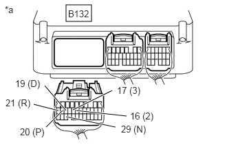
| *a | Rear view of wire harness connector
(to Transmission Control ECU Assembly) |
Measure the voltage according to the value(s) in the table below.
- Standard Voltage:
Tester Connection Condition Specified Condition B132-20 (P) - Body ground ·Ignition switch ON
·Shift lever in P
11 to 14 V ·Ignition switch ON
·Shift lever not in P
Below 1 V B132-21 (R) - Body ground ·Ignition switch ON
·Shift lever in R
11 to 14 V ·Ignition switch ON
·Shift lever not in R
Below 1 V B132-29 (N) - Body ground ·Ignition switch ON
·Shift lever in N
11 to 14 V ·Ignition switch ON
·Shift lever not in N
Below 1 V B132-19 (D) - Body ground ·Ignition switch ON
·Shift lever in D
11 to 14 V ·Ignition switch ON
·Shift lever not in D
Below 1 V B132-17 (3) - Body ground ·Ignition switch ON
·Shift lever in 4
11 to 14 V ·Ignition switch ON
·Shift lever not in 4
Below 1 V B132-16 (2) - Body ground ·Ignition switch ON
·Shift lever in 2/L
11 to 14 V ·Ignition switch ON
·Shift lever not in 2/L
Below 1 V
- Result:
Proceed to OK NG
OK
NG