N04C-WA ENGINE CONTROL ECD SYSTEM P0101 Mass or Volume Air Flow Sensor "A" Circuit Range/Performance
DESCRIPTION
| DTC No. | Detection Item | DTC Detection Condition | Trouble Area | MIL | Memory |
|---|---|---|---|---|---|
| P0101 | Mass or Volume Air Flow Sensor "A" Circuit Range/Performance | Diagnosis Condition:
·
Engine speed is between 570 and 1200 rpm ·
Fuel injection rate is between 0 and 35 mm3/st ·
Engine coolant temperature is 55°C (131°F) or less ·
EGR valve opening is 0% or less (EGR-cut status) ·
Exhaust brake is not actuated Malfunction Status: ·
Theoretical air quantity calculated from boost pressure and atmospheric pressure and actual air quantity are compared for at least 10 seconds, and the ratio of theoretical air quantity to actual air quantity is at least 1.15 or no greater than 0.75. ·
Difference between DCY value prior to above result and current DCY value is 0.10 or less ·
The condition "(Average boost pressure minus average atmospheric pressure) was 18 kPa or more" when the ignition switch off and engine was stopped after previous DCY is not continued for more than 3 seconds. Malfunction Duration: 1 seconds or more |
·
Harness or connector ·
EGR valve assembly ·
Diesel throttle body ·
Intercooler assembly ·
ECM |
Class B1 | DTC stored |
MONITOR DESCRIPTION
The mass air flow meter mounted on the air cleaner constantly measures the intake air quantity.
CONFIRMATION DRIVING PATTERN
| DTC No. | DTC Detection Drive Pattern |
|---|---|
| P0101 | Idle the engine for 15 seconds. |
WIRING DIAGRAM
Refer to DTC P0104.
Click hereEngine / Hybrid System>N04C-WA (ENGINE CONTROL)>ECD SYSTEM>P0104
CAUTION / NOTICE / HINT
- NOTICE:
-
After replacing the ECM, the new ECM needs registration (Click hereEngine / Hybrid System>N04C-WA (ENGINE CONTROL)>ECD SYSTEM>REGISTRATION) and initialization (Click hereEngine / Hybrid System>N04C-WA (ENGINE CONTROL)>ECD SYSTEM>INITIALIZATION).
- HINT:
-
Read freeze frame data using the GTS. Freeze frame data records the engine condition when malfunctions are detected. When troubleshooting, freeze frame data can help determine if the vehicle was moving or stationary, if the engine was warmed up or not, and other data from the time the malfunction occurred.
PROCEDURE
Inspect the air cleaner filter element sub-assembly is dirty, clogged or damaged.
Make sure the element is a genuine part.
- Result:
Proceed to OK NG
OK
NG
Check the intake system.
Check the intake hose and verify that there are no disconnections, clogging, punctures, or cracks.
Check the breather hose and verify that there are no disconnections, clogging, punctures, or cracks.
Check the intercooler hose and verify that there are no disconnections, clogging, punctures, or cracks.
- Result:
Proceed to OK NG
OK
NG
Check the installation of the mass air flow meter.
Make sure there is no dirt, damage or clogging in the sensing unit of the mass air flow meter.
- Result:
Proceed to OK NG
OK
NG
Disconnect the ECM connector.
Disconnect the mass air flow meter connector.
Connect the signal check harness to the ECM vehicle side harness. (Do not connect harness to the ECM)
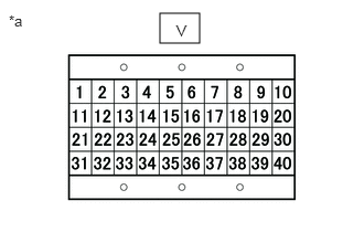
| *a | Signal Check Harness Lead Connector |
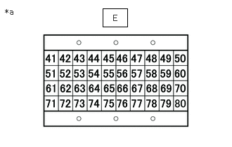
| *a | Signal Check Harness Lead Connector |
Measure the resistance according to the value(s) in the table below.
- Standard Resistance:
Tester Connection Condition Specified Condition V-1 - Body ground and other terminals Always 10 kΩ or higher E-57 - Body ground and other terminals Always 10 kΩ or higher E-74 - Body ground and other terminals Always 10 kΩ or higher
- Result:
Proceed to OK NG
OK
NG
Disconnect the ECM connector.
Disconnect the mass air flow meter connector.
Connect the signal check harness to the ECM vehicle side harness. (Do not connect harness to the ECM)
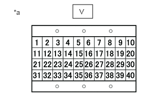
| *a | Signal Check Harness Lead Connector |
| *a | Signal Check Harness Lead Connector |
Measure the resistance according to the value(s) in the table below.
- Standard Resistance:
Tester Connection Condition Specified Condition V-1 - B51-3 (+B) Always Below 1 Ω E-57 - B51-4 (E2G) Always Below 1 Ω E-74 - B51-5 (FG) Always Below 1 Ω
- Result:
Proceed to OK NG
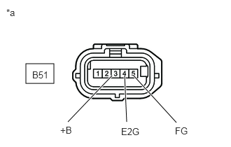
| *a | Front view of wire harness connector
(to Mass Air Flow Meter) |
OK
NG
Replace the mass air flow meter.
- Result:
Proceed to NEXT
NEXT
Connect the GTS to the DLC3.
Turn the ignition switch to ON and turn the GTS on.
Clear the DTCs.
- HINT:
-
Clear the DTCs with the engine stopped, as DTCs cannot be cleared while the engine is running.
Turn the ignition switch off for 30 seconds or more.
Perform the confirmation driving pattern.
Turn the GTS on.
Enter the following menus: Powertrain / Engine / Trouble Codes.
Read Current DTCs.
- Result:
Result Proceed to DTC P0101 is output A DTCs are not output B
A
B
Inspect the EGR valve for damage due to foreign substances.
Check if there is soot obstructing the exhaust gas passageway inlet or outlet.
- Result:
Proceed to OK NG
OK
NG
Connect the GTS to the DLC3.
Turn the ignition switch to ON and turn the GTS on.
Enter the following menus: Powertrain / Engine / Active Test / Control the EGR Valve Position / Data List / Actual EGR Valve Position and Target EGR Valve Position
Check each step from 90 to 0% of the time lag of the target EGR valve opening and actual EGR valve opening.
- NOTICE:
-
Perform the inspection while the engine is stopped to avoid engine damages.
- Standard:
The response delay should be less than 5 seconds.
- Result:
Proceed to OK NG
OK
NG
Check the operating status of the diesel throttle body (for incorrect opening or sticky valve).
- Result:
Proceed to OK NG
OK
NG
Check if there is an obstruction due to clogging inside the intercooler assembly.
- Result:
Proceed to OK NG
OK
NG
Connect the GTS to the DLC3.
Turn the ignition switch to ON and turn the GTS on.
Clear the DTCs.
- HINT:
-
Clear the DTCs with the engine stopped, as DTCs cannot be cleared while the engine is running.
Turn the ignition switch off for 30 seconds or more.
After starting the engine, warm it up until the engine coolant temperature is 80°C or more.
Turn the GTS on.
Enter the following menus: Powertrain / Engine / Trouble Codes.
Read Current DTCs.
- Result:
Result Proceed to DTC P0101 is output A DTCs are not output B
A
B
Replace the ECM.
Click hereEngine / Hybrid System>N04C-WA (ENGINE CONTROL)>ECM>REMOVAL
- Result:
Proceed to NEXT
NEXT
Connect the GTS to the DLC3.
Turn the ignition switch to ON and turn the GTS on.
Clear the DTCs.
- HINT:
-
Clear the DTCs with the engine stopped, as DTCs cannot be cleared while the engine is running.
Turn the ignition switch off for 30 seconds or more.
After starting the engine, warm it up until the engine coolant temperature is 80°C or more.
Turn the GTS on.
Enter the following menus: Powertrain / Engine / Trouble Codes.
Confirm that the DTC is not output again.
- Result:
Proceed to NEXT
NEXT
Repair or replace the harness or connector.
- Result:
Proceed to NEXT
NEXT
Clean the intercooler assembly.
- HINT:
-
Replace it as needed.
- Result:
Proceed to NEXT
NEXT
Mass air flow meter carry out air blow from the suction port of the main body and install it properly.
- HINT:
-
If damaged, replace the mass air flow meter.
- Result:
Proceed to NEXT
NEXT
Clean or replace the diesel throttle body.
- HINT:
-
Replace it as needed.
- Result:
Proceed to NEXT
NEXT
Repair or replace the intake system.
- Result:
Proceed to NEXT
NEXT
Replace the EGR valve assembly.
Click hereEngine / Hybrid System>N04C-WA (EMISSION CONTROL)>EGR VALVE>REMOVAL
- Result:
Proceed to NEXT
NEXT
Repair or replace the air cleaner filter element sub-assembly.
- Result:
Proceed to NEXT
NEXT
Remove foreign substances and clean the valve.
- HINT:
-
Replace the EGR valve assembly if it is damaged.
- Result:
Proceed to NEXT
NEXT