N04C-WA EMISSION CONTROL EGR COOLER INSTALLATION
PROCEDURE

 17505G
1.INSTALL NO. 1 EXHAUST PIPE HEAT INSULATOR SUB-ASSEMBLY
Install the No. 1 exhaust pipe heat insulator sub-assembly with the 3 bolts.
- Torque:
- 28.5 N*m (291 kgf*cm, 21 ft.*lbf)
25608
2.INSTALL EGR COOLER SUB-ASSEMBLY
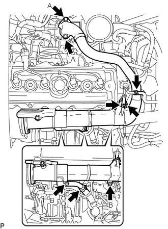
Connect the No. 1 water by-pass hose and No. 2 water by-pass hose.
Connect the water by-pass hose and reserve tank hose.
Install a new gasket and the EGR cooler sub-assembly with the 4 bolts.
- Torque:
- for bolt A : 55 N*m (561 kgf*cm, 41 ft.*lbf)
- for bolt B : 68.5 N*m (699 kgf*cm, 51 ft.*lbf)
Temporarily install the EGR pipe connector to the EGR cooler sub-assembly and exhaust manifold with the 2 new gaskets, 3 spacers, 3 nuts and 2 bolts.
- NOTICE:
-
Tighten the nuts until they contact the EGR cooler sub-assembly.
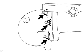
Tighten the 3 nuts.
- Torque:
- 68.5 N*m (699 kgf*cm, 51 ft.*lbf)
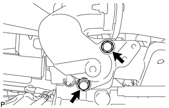
Tighten the 2 bolts.
- Torque:
- 68.5 N*m (699 kgf*cm, 51 ft.*lbf)
17505H
3.INSTALL NO. 2 EXHAUST PIPE HEAT INSULATOR SUB-ASSEMBLY
Install the No. 2 exhaust pipe heat insulator sub-assembly with the 2 bolts.
- Torque:
- 28.5 N*m (291 kgf*cm, 21 ft.*lbf)
4.INSTALL NO. 2 TURBO INSULATOR
Install the No. 2 turbo insulator with the 3 bolts.
- Torque:
- 28.5 N*m (291 kgf*cm, 21 ft.*lbf)
5.INSTALL NO. 3 TURBO INSULATOR
Install the No. 3 turbo insulator with the 4 bolts.
- Torque:
- 28.5 N*m (291 kgf*cm, 21 ft.*lbf)
11409
6.INSTALL ENGINE OIL LEVEL DIPSTICK GUIDE
Install a new O-ring to the engine oil level dipstick guide.
Install the engine oil level dipstick guide with the bolt.
- Torque:
- 28.5 N*m (291 kgf*cm, 21 ft.*lbf)
Attach the 2 wire harness clamps.
12203
7.INSTALL PCV PIPE SUB-ASSEMBLY
Install the pcv pipe sub-assembly with the 2 bolts.
- Torque:
- 28.5 N*m (291 kgf*cm, 21 ft.*lbf)
Connect the No. 2 pcv hose and slide the clip to secure it.
Connect the pcv hose and slide the 2 clips to secure it.
44379A
8.INSTALL NO. 2 OIL RESERVOIR BRACKET
Install the No. 2 oil reservoir bracket with the 3 bolts.
- Torque:
- 12 N*m (122 kgf*cm, 9 ft.*lbf)
44360
9.INSTALL VANE PUMP OIL RESERVOIR ASSEMBLY
Install the vane pump oil reservoir assembly with the 3 bolts.
- Torque:
- 18 N*m (184 kgf*cm, 13 ft.*lbf)
12601B
10.INSTALL NO. 1 ENGINE COVER SUB-ASSEMBLY
17341F
11.INSTALL NO. 1 AIR HOSE
Install the No. 1 air hose to the turbo charger sub-assembly and tighten the hose clamp.
- Torque:
- 5.0 N*m (51 kgf*cm, 44 in.*lbf)
Install the No. 1 air hose with the bolt.
- Torque:
- 18 N*m (184 kgf*cm, 13 ft.*lbf)
Connect the No. 3 pcv hose with the hose clamp.
Attach the 4 wire harness clamps to the No. 1 air hose.
17700
12.INSTALL AIR CLEANER ASSEMBLY
17113D
13.INSTALL INTAKE PIPE
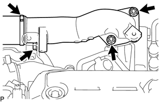
Install a new gasket and the intake pipe with the 2 nuts and bolt.
- Torque:
- 28.5 N*m (291 kgf*cm, 21 ft.*lbf)
Connect the No. 1 intercooler air hose with the clamp.
- Torque:
- 6.0 N*m (61 kgf*cm, 53 in.*lbf)
53711C
14.INSTALL FRONT FENDER APRON RH
15.INSTALL EXHAUST GAS TEMPERATURE SENSOR (for EGR Cooler Side)
16.ADD ENGINE COOLANT
17.INSPECT FOR COOLANT LEAK
18.INSPECT FOR EXHAUST GAS LEAK
58701A
19.INSTALL FRONT ENGINE SERVICE COVER PANEL SUB-ASSEMBLY
33820B
20.CONNECT TRANSMISSION CONTROL CABLE ASSEMBLY
58841A
21.INSTALL SHIFTING HOLE COVER (for Automatic Transmission)
58123A
22.INSTALL SHIFT AND SELECT LEVER SUPPORT WITH BOOTS (for Manual Transmission)
58420
23.INSTALL NO. 2 ENGINE SERVICE HOLE COVER ASSEMBLY
58734B
24.INSTALL REAR ENGINE SERVICE COVER WEATHERSTRIP
58410
25.INSTALL ENGINE SERVICE HOLE COVER
58521D
26.INSTALL ENGINE SERVICE HOLE COVER MAT